

Description
-
Model List:
- D475A-8E0 Bull Dozer
- D475Ai-8E0 Bull Dozer
- 1. Cover
- 1.1. FOREWORD
- 1.2. CONTENTS
- 1.3. PRECAUTIONS FOR FIELD ASSEMBLY
- 1.4. DISPOSAL OF REMOVED PARTS
- 1.5. ASSEMBLY PROCEDURE, NECESSARY EQUIPMENTS, AND SCHEDULE
- 1.6. KIT LAYOUT DIAGRAM (WORK SPACE LAYOUT)
- 1.7. PACKING STYLE FOR TRANSPORTATION
- 1.8. SPECIFICATIONS
- 1.9. TOOL LIST FOR FIELD ASSEMBLY
- 1.10. DIAGRAM FOR TOOLS
- 1.11. TIGHTEN TORQUE TABLE
- 1.12. COATING MATERIALS LIST
- 1.13. SELECTION OF WIRE ROPES USED FOR ASSEMBLY
- 1.14. SELECTION OF NYLON SLINGS USED FOR ASSEMBLY
- 1.15. ASSEMBLY PROCEDURE
- 1.15.1. A1 Installation of track shoe assembly
- 1.15.2. A2 Installation of machine body (chassis)
- 1.15.3. A3 Installation of operators cab assembly (When operator cab assembly is not installed)
- 1.15.4. A4 Installation of pivot shaft (When pivot shaft is not installed)
- 1.15.5. A5 Installation of final drive assembly
- 1.15.6. A6 Installation of undercover (When undercover is not installed)
- 1.15.7. A7 Installation of blade lift hydraulic cylinder
- 1.15.8. A8 Installation of undercarriage 1
- 1.15.9. A8 Installation of undercarriage 2
- 1.15.10. A9 Adding oil to pivot chamber
- 1.15.11. A10 Inspection of oil level and coolant level
- 1.15.12. A11 Installation of ripper1 (Machine with ripper)
- 1.15.13. A11 Installation of ripper2 (Machine with ripper)
- 1.15.14. A11 Installation of ripper3 (Machine with ripper)
- 1.15.15. A11 Installation of ripper4 (Machine with ripper)
- 1.15.16. A11 Installation of ripper5 (Machine with ripper)
- 1.15.17. A11 Installation of ripper6 (Machine with ripper)
- 1.15.18. A11 Installation of counterweight (Machine with counterweight)
- 1.15.19. A12 Installation of trunnion
- 1.15.20. A13 Installation of track
- 1.15.21. A14 Adjusting of track tension
- 1.15.22. A15 Installation of mask
- 1.15.23. A16 Installation of handrail / step on right side of radiator
- 1.15.24. A17 Installation of handrail / step on left side of radiator
- 1.15.25. A18 Instalation of cab right side cover (When cab right side cover is not installed)
- 1.15.26. A19 Instalation of cab left side cover (When cab left side cover is not installed)
- 1.15.27. A20 Assembling of blade unit1 (Machine with semiU blade/fullU blade)
- 1.15.28. A20 Assembling of blade unit2 (Machine with semiU blade/fullU blade)
- 1.15.29. A20 Assembling of blade unit3 (Machine with semiU blade/fullU blade)
- 1.15.30. A20 Assembling of blade unit4 (Machine with semiU blade/fullU blade)
- 1.15.31. A20 Assembling of blade unit5 (Machine with semiU blade/fullU blade)
- 1.15.32. A20 Assembling of blade unit1 (Machine with superdozer blade)
- 1.15.33. A20 Assembling of blade unit2 (Machine with superdozer blade)
- 1.15.34. A20 Assembling of blade unit3 (Machine with superdozer blade)
- 1.15.35. A20 Assembling of blade unit4 (Machine with superdozer blade)
- 1.15.36. A20 Assembling of blade unit5 (Machine with superdozer blade)
- 1.15.37. A21 Installation of blade assembly (Machine with semiU blade/fullU blade)
- 1.15.38. A21 Installation of blade assembly (Machine with superdozer blade)
- 1.15.39. A22 Installation of KOMTRAX antenna
- 1.15.40. A23 Installation of ROPS
- 1.15.41. A24 Installation of engine air intake port hood (When engine air intake port hood is not installed)
- 1.15.42. A25 Installation of precleaner (optional) (When precleaner is not installed)
- 1.15.43. A26 Installation of engine exhaust pipe (When engine exhaust pipe is not installed)
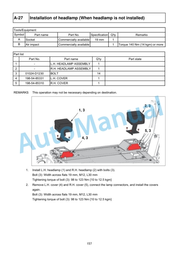
- 1.15.44. A27 Installation of headlamp (When headlamp is not installed)
- 1.15.45. A28 Installation of giant ripper shank
- 1.15.46. A29 Adjustment of blade tilt control angle (Machine with semiU blade/fullU blade)
- 1.15.47. A30 Adjustment of blade tilt control angle (Machine with superdozer)
- 1.15.48. A31 Blade pitch current value correction (Machine with superdozer)
- 1.15.49. A32 Installation of platform1
- 1.15.50. A32 Installation of platform2
- 1.15.51. A32 Installation of platform3
- 1.15.52. A32 Installation of platform4
- 1.15.53. A33 Greasing each part
- 1.15.54. A34 Bleeding air from hydraulic cylinder
- 1.15.55. A35 Bleeding air from work equipment pump and fan pump
- 1.15.56. A36 Installation of quick charge piping (optional)
- 1.15.57. A37 Installation of ladder 1 (For machine with ladder)
- 1.15.58. A37 Installation of ladder 2 (For machine with ladder)
- 1.15.59. A37 Installation of ladder 3 (For machine with ladder)
- 1.15.60. A37 Installation of ladder 4 (For machine with ladder)
- 1.15.61. A37 Installation of ladder 5 (For machine with ladder)
- 1.15.62. A38 Installation of ladder 1 (For machine with retrofitting ladder)
- 1.15.63. A38 Installation of ladder 2 (For machine with retrofitting ladder)
- 1.15.64. A38 Installation of ladder 3 (For machine with retrofitting ladder)
- 1.15.65. A38 Installation of ladder 4 (For machine with retrofitting ladder)
- 1.15.66. A38 Installation of ladder 5 (For machine with retrofitting ladder)
- 1.15.67. A38 Installation of ladder 6 (For machine with retrofitting ladder)
- 1.15.68. A39 Installation of access light and additional work lamp (optional)
- 1.15.69. A40 Installation of stroke sensing blade lift cylinder (For ICT specification)
- 1.15.70. A41 Installation of stroke sensor harness (When installing the ICT local modification kit)
- 1.15.71. A42 Installation of IMU sensor (When installing the ICT local modification kit)
- 1.15.72. A43 Installation of ICT harness (When installing the ICT local modification kit)
- 1.15.73. A44 Installation of AUX BOX (For ICT specification)
- 1.15.74. A45 Installation of navigation controller (When installing the ICT local modification kit)
- 1.15.75. A46 Installation of control box (When installing the ICT local modification kit)
- 1.15.76. A47 Installation of offset switch (When installing the ICT local modification kit)
- 1.16. CHECK AND MAINTENANCE PROCEDURES AFTER COMPLETION OF ASSEMBLY
- 1.16.1. M1 Checking machine monitor 1
- 1.16.2. M1 Checking machine monitor 2
- 1.16.3. M1 Checking machine monitor 3
- 1.16.4. M1 Checking machine monitor 4
- 1.16.5. M1 Checking machine monitor 5
- 1.16.6. M2 Adjustment menu
- 1.16.7. M3 Change of return filter (Standard filter Flushing filter)
- 1.16.8. M4 Flushing hydraulic circuit and bleeding air from cylinder 1
- 1.16.9. M5 Change of return filter (Flushing filter Standard filter)
- 1.16.10. M6 Bleeding air from cylinder 2
- 1.16.11. M7 How to start operation of KOMTRAX terminal and how to initializeKOMTRAX Plus controller
- 1.16.12. M8 Noinjection cranking of engine
- 1.16.13. M9 Calibration of cutting edge
- 1.17. APPENDIX 1 INSTALLATION OF SPILL GUARDS
- 1.18. APPENDIX 2 FIELD ASSEMBLY INSPECTION REPORT
- 1.19. APPENDIX 3 PmCLINIC










Reviews
There are no reviews yet.