
Description
-
Model List:
- GD535-5 Motor Grader
- 1. Notice of revision
- 2. Index and foreword
- 2.1. Index and foreword
- 2.1.1. Table of contents
- 2.1.2. Acronyms
- 2.1.3. Foreword and general information
- 3. Specification
- 3.1. Specification
- 3.1.1. Contents
- 3.1.2. Acronyms
- 3.1.3. Specifications
- 4. Structure and function
- 4.1. Structure and function
- 4.1.1. Contents
- 4.1.2. Acronyms
- 4.1.3. Engine and cooling system
- 4.1.4. Power train system
- 4.1.5. Steering system
- 4.1.6. Brake system
- 4.1.7. Undercarriage and frame
- 4.1.8. Hydraulic system
- 4.1.9. Work equipment system
- 4.1.10. Cab and its attachments
- 4.1.11. Electrical system
- 5. Standard value table
- 5.1. Standard value table
- 5.1.1. Contents
- 5.1.2. Acronyms
- 5.1.3. Standard value table
- 6. Testing and adjusting
- 6.1. Testing and adjusting
- 6.1.1. Contents
- 6.1.2. Acronyms
- 6.1.3. Tools for testing, adjusting, and troubleshooting
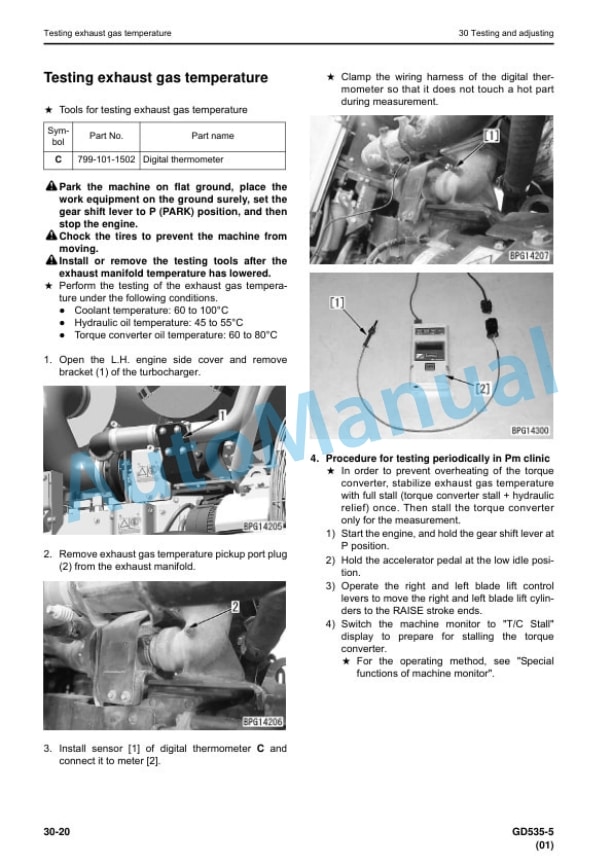
- 6.1.4. Engine and cooling system
- 6.1.5. Power train
- 6.1.6. Steering system
- 6.1.7. Brake system
- 6.1.8. Hydraulic system
- 6.1.9. Work equipment
- 6.1.10. Electrical system
- 6.1.11. Pm Clinic
- 7. Troubleshooting
- 7.1. Troubleshooting
- 7.1.1. Contents
- 7.1.2. Acronyms
- 7.1.3. Information related to troubleshooting
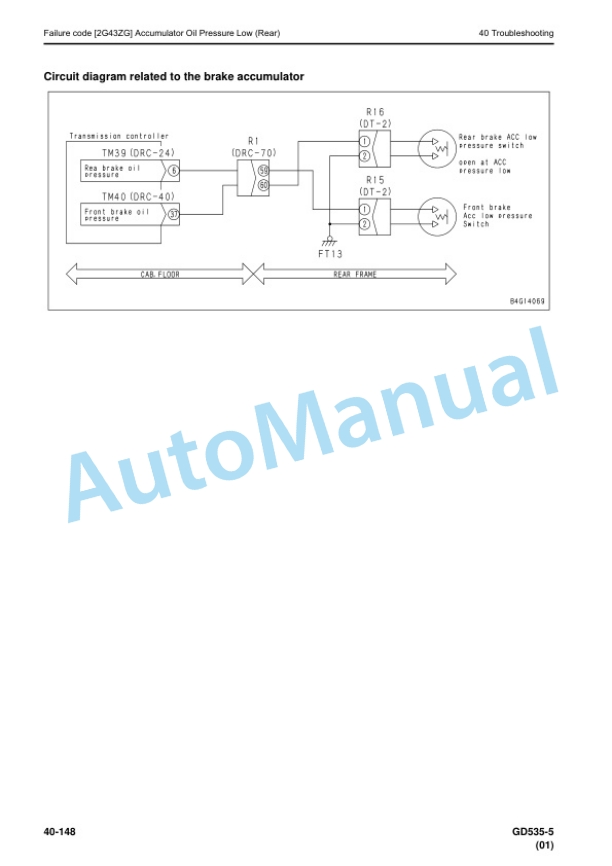
- 7.1.4. Troubleshooting by failure code (display of code)
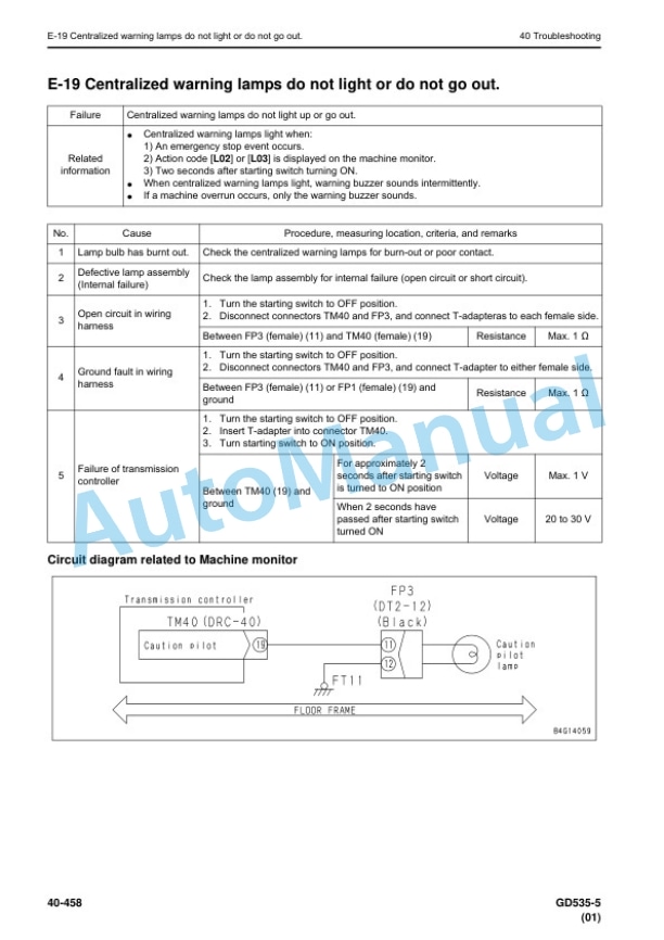
- 7.1.5. Troubleshooting of electrical system (Emode)
- 7.1.6. Troubleshooting of hydraulic and mechanical system (Hmode)
- 7.1.7. Troubleshooting of engine (Smode)
- 8. Disassembly and assembly
- 8.1. Contents
- 8.2. Acronyms
- 8.3. Related information on disassembly and assembly
- 8.3.1. How to read this manual
- 8.3.2. Coating materials list
- 8.3.3. Special tool list
- 8.3.4. Sketches of special tools
- 8.4. Engine and cooling system
- 8.4.1. Removal and installation of supply pump assembly
- 8.4.2. Removal and installation of injector assembly
- 8.4.3. Removal and installation of cylinder head assembly
- 8.4.4. Removal and installation of air conditioner compressor belt
- 8.4.5. Removal and installation of alternator belt
- 8.4.6. Removal and installation of engine front oil seal
- 8.4.7. Removal and installation of engine rear oil seal
- 8.4.8. Removal and installation of cooling fan pump assembly
- 8.4.9. Removal and installation of cooling fan and fan motor assembly
- 8.4.10. Removal and installation of radiator assembly
- 8.4.11. Removal and installation of aftercooler assembly
- 8.4.12. Removal and installation of power train oil cooler assembly
- 8.4.13. Removal and installation of fuel tank assembly
- 8.4.14. Removal and installation of engine hood assembly
- 8.4.15. Removal and installation of air conditioner compressor assembly
- 8.5. Power train
- 8.5.1. Removal and installation of engine, transmission, and torque converter assembly
- 8.5.2. Disconnection and connection of engine, transmission, and torque converter assembly
- 8.5.3. Disassembly and assembly of torque converter assembly
- 8.5.4. Disassembly and assembly of transmission assembly
- 8.5.5. Removal and installation of tandem drive and final drive assembly
- 8.5.6. Disassembly and assembly of tandem drive assembly
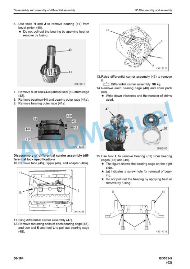
- 8.5.7. Disassembly and assembly of differential assembly
- 8.5.8. Disassembly and assembly of final drive assembly
- 8.6. Steering system
- 8.6.1. Removal and installation of Orbitrol valve assembly
- 8.7. Brake system
- 8.7.1. Disassembly and assembly of wheel brake assembly
- 8.8. Undercarriage and frame
- 8.8.1. Removal and installation of center hinge pin
- 8.9. Hydraulic system
- 8.9.1. Removal and installation of hydraulic tank, battery, and frame assembly
- 8.9.2. Removal and installation of hydraulic tank assembly
- 8.9.3. Removal and installation of control valve assembly
- 8.9.4. Disassembly and assembly of hydraulic cylinder assembly
- 8.10. Work equipment
- 8.10.1. Removal and installation of blade assembly
- 8.10.2. Removal and installation of circle drawbar assembly
- 8.10.3. Removal and installation of circle rotation gear assembly
- 8.10.4. Disassembly and assembly of circle rotation gear assembly
- 8.11. Cab and its attachments
- 8.11.1. Removal and installation of operators cab assembly
- 8.11.2. Removal and installation of operator cab glass (adhered glass)
- 8.11.3. Removal and installation of floor frame assembly
- 8.11.4. Removal and installation of operators cab and floor frame assembly
- 8.11.5. Removal and installation of air conditioner unit assembly
- 8.11.6. Removal and installation operators seat
- 8.11.7. Removal and installation seat belt
- 8.12. Electrical system
- 8.12.1. Removal and installation of engine controller assembly
- 8.12.2. Removal and installation of machine monitor assembly
- 8.12.3. Removal and installation of transmission controller assembly
- 8.12.4. Removal and installation of rearview camera
- 8.12.5. Removal and installation of KOMTRAX terminal assembly
- 8.13. Disassembly and assembly
- 9. Maintenance standard
- 9.1. Maintenance standard
- 9.1.1. Contents
- 9.1.2. Acronyms
- 9.1.3. Engine and cooling system
- 9.1.4. Power train system
- 9.1.5. Steering system
- 9.1.6. Brake system
- 9.1.7. Undercarriage and frame
- 9.1.8. Hydraulic system
- 9.1.9. Work equipment
- 10. Appendix
- 10.1. Appendix
- 10.1.1. Contents
- 10.1.2. Acronyms
- 10.1.3. Air conditioner system
- 10.1.4. Component parts of air conditioner system
- 10.1.5. Testing air leakage (duct)
- 10.1.6. Check temperature control function
- 10.1.7. Testing fresh/recirc air changeover
- 10.1.8. Test evaporator temperature sensor
- 10.1.9. Test relays
- 10.1.10. Check blower AMP
- 10.1.11. Connection of service tool
- 11. Diagrams and drawings
- 11.1. Contents
- 11.2. Acronyms
- 11.3. Hydraulic diagrams and drawings
- 11.3.1. Symbols used in hydraulic circuit diagrams
- 11.4. Hydraulic circuit diagram
- 11.4.1. Hydraulic circuit diagram (1/2)
- 11.4.2. Hydraulic circuit diagram (2/2)
- 11.5. Power train hydraulic circuit diagram
- 11.5.1. Power train hydraulic circuit diagram
- 11.6. Electrical diagrams and drawings
- 11.6.1. Symbols used in electric circuit diagrams
- 11.6.2. Chassis electric circuit diagram
- 11.6.3. Floor electric circuit diagram
- 11.7. Chassis electric circuit diagram
- 11.7.1. Chassis electric circuit diagram (1/5)
- 11.7.2. Chassis electric circuit diagram (2/5)
- 11.7.3. Chassis electric circuit diagram (3/5)
- 11.7.4. Chassis electric circuit diagram (4/5)
- 11.7.5. Chassis electric circuit diagram (5/5)
- 11.7.6. Floor electric circuit diagram (1/7)
- 11.7.7. Floor electric circuit diagram (2/7)
- 11.7.8. Floor electric circuit diagram (3/7)
- 11.7.9. Floor electric circuit diagram (4/7)
- 11.7.10. Floor electric circuit diagram (5/7)
- 11.7.11. Floor electric circuit diagram (6/7)
- 11.7.12. Floor electric circuit diagram (7/7)


Reviews
There are no reviews yet.