
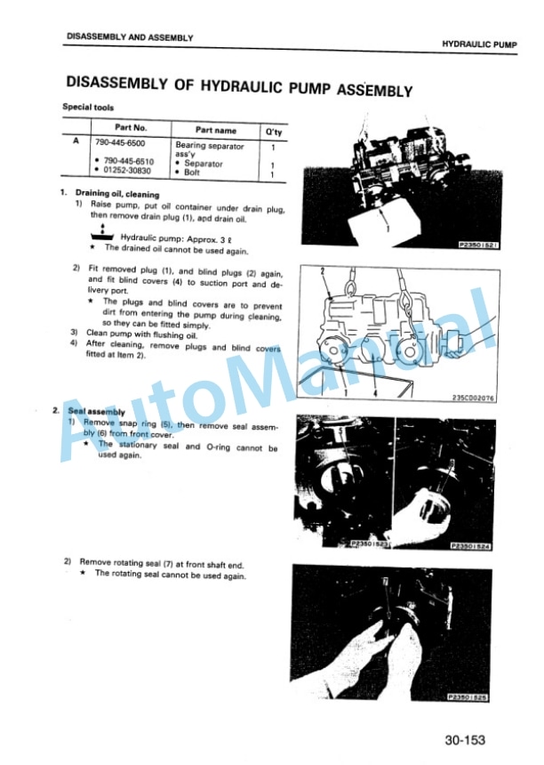
Description
-
Model List:
- GD825A-2 Motor Grader
- 1. COVER
- 2. GENERAL
- 2.1. Specification dimension drawings
- 2.2. Specifications
- 2.3. Weight table
- 2.4. Fuel, coolant and lubricants
- 3. STRUCTURE AND FUNCTION
- 3.1. General
- 3.2. Power train diagram
- 3.3. Joint
- 3.4. HYDROSHIFT transmission and transfer Piping
- 3.5. Hydraulic circuit for power train
- 3.6. Hydraulic circuit diagram for power train
- 3.7. Transmission filter relief valve
- 3.8. PTO (Power Take Off)
- 3.9. HYDROSHIFT transmission and transfer
- 3.10. Transmission control valve
- 3.11. Transmission control
- 3.12. Inching control
- 3.13. Drive shaft
- 3.14. Final drive, differential lock and unlock piping
- 3.15. Final drive
- 3.16. Tandem drive
- 3.17. Steering piping
- 3.18. Steering circuit system
- 3.19. Steering circuit diagram
- 3.20. Steering valve
- 3.21. Double relief valve
- 3.22. Check valve
- 3.23. Emergency steering system
- 3.24. Front axle
- 3.25. Wheel
- 3.26. Air piping
- 3.27. Air circuit diagram
- 3.28. Alcohol injector
- 3.29. Disc brake
- 3.30. Parking brake
- 3.31. Brake air piping
- 3.32. Brake air circuit system
- 3.33. Brake air circuit diagram
- 3.34. Air drier
- 3.35. Air governor
- 3.36. Air tank
- 3.37. Automatic drain valve
- 3.38. Check valve
- 3.39. Brake valve
- 3.40. Parking brake system
- 3.41. Parking brake solenoid valve
- 3.42. Exhaust valve
- 3.43. Spring cylinder
- 3.44. Hydraulic control piping
- 3.45. Hydraulic circuit system
- 3.46. Hydraulic circuit diagram
- 3.47. Closed center load sensing system (CLSS)
- 3.48. Hydraulic pump
- 3.49. Priority divider valve
- 3.50. Surge pressure absorbing valve
- 3.51. Hydraulic control valve
- 3.52. Pressure compensating mechanism of hydraulic control valve
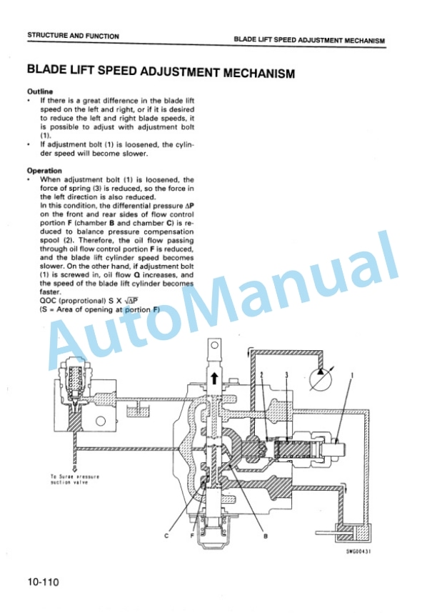
- 3.53. Blade lift speed adjustment Mechanism
- 3.54. Pilot check valve
- 3.55. Pilot check valve (with safety valve)
- 3.56. Circle rotation motor
- 3.57. Blade accumulator system
- 3.58. Blade float system
- 3.59. Drawbar and lifter
- 3.60. Blade
- 3.61. Lifter bracket control piping
- 3.62. Circle rotation gear
- 3.63. Rear mount ripper
- 3.64. Hydraulic control linkage
- 3.65. Main frame
- 3.66. Air conditioner
- 3.67. Electrical wiring diagram
- 3.68. Monitor panel, cluster gauge and pilot lamp
- 3.69. Electrical circuit diagram
- 3.70. Electrical vehicle monitoring system (EVMS)
- 3.71. Transmission control system
- 3.72. Sensors
- 3.73. Engine starting circuit
- 3.74. Engine stopping circuit
- 4. TESTING AND ADJUSTING
- 4.1. Standard value table for engine
- 4.2. Standard value table for testing and adjusting, failure judgment of chassis
- 4.3. Tool list for testing and adjusting
- 4.4. Testing and adjusting valve clearance
- 4.5. Measuring compression pressure
- 4.6. Testing and adjusting fuel injection timing
- 4.7. Measuring blowby pressure
- 4.8. Measuring engine oil pressure
- 4.9. Measuring exhaust gas color
- 4.10. Measuring exhaust gas temperature
- 4.11. Measuring intake air pressure (boost pressure)
- 4.12. Testing and adjusting fan belt tension
- 4.13. Testing and adjusting alternator belt tension
- 4.14. Procedure for adjusting the engine stop motor cable
- 4.15. Adjusting accelerator control
- 4.16. Inching pedal travel and operating force
- 4.17. Measuring transmission oil pressure
- 4.18. Checking differential locking device oil pressure
- 4.19. Steering system
- 4.20. Checking tire runout
- 4.21. Checking toein
- 4.22. Installation of articulate center pins
- 4.23. Checking wear of disc
- 4.24. Checking work equipment control lever travel and operating force
- 4.25. Checking work equipment hydraulic pressure
- 4.26. Adjusting work equipment hydraulic pressure
- 4.27. Measuring hydraulic drift
- 4.28. Charging blade accumulator with gas
- 4.29. Adjusting blade lift speed
- 4.30. Bleeding air from hydraulic pump
- 4.31. Adjusting slip load of circle rotation clutch
- 4.32. Adjusting clearance of F and R switches
- 4.33. Adjusting shift potentiometer
- 4.34. Adjusting inching potentiometer
- 4.35. Transmission controller
- 4.36. Adjusting speedometer module of machine monitor
- 4.37. PmCLINIC
- 4.38. TROUBLESHOOTING
- 4.38.1. Points to remember when troubleshooting
- 4.38.2. Sequence of events in troubleshooting
- 4.38.3. Points to remember when carrying out maintenance
- 4.38.4. Checks before troubleshooting
- 4.38.5. Electrical circuit system diagram
- 4.38.6. Connector types and mounting locations
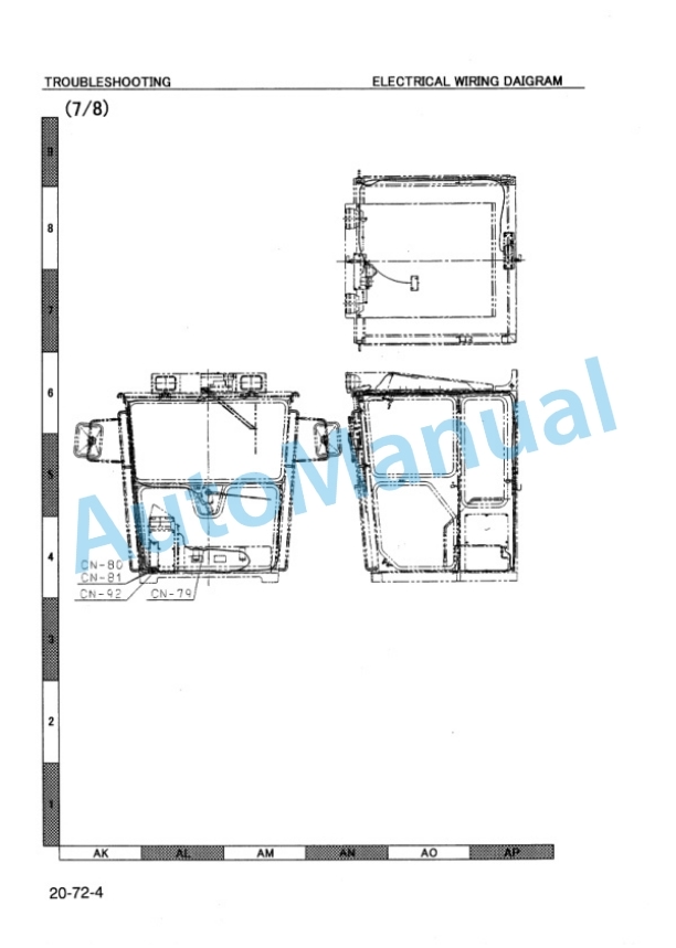
- 4.38.7. Electrical wiring diagram
- 4.38.8. Connection table for connector pin numbers
- 4.38.9. Method of using troubleshooting charts
- 4.38.10. TROUBLESHOOTING OF ENGINE (S MODE)
- 4.38.11. TROUBLESHOOTING CHART FOR ELECTRONIC VEHICLE MONITORING SYSTEM (M MODE)
- 4.38.12. TROUBLESHOOTING CHART FOR ELECTRONIC (ENGINE, PARKING BRAKE, TRANSMISSION CONTROL) (E MODE)
- 4.38.13. TROUBLESHOOTING OF TRANSMISSION CONTROLLER SYSTEM (ET MODE)
- 4.38.14. TROUBLESHOOTING CHART FOR HYDRAULIC SYSTEM (H MODE)
- 5. DISASSEMBLY AND ASSEMBLY
- 5.1. COATING MATERIALS LIST
- 5.2. SPECIAL TOOL LIST
- 5.3. STARTING MOTOR
- 5.3.1. Removal and Installation
- 5.4. ALTERNATOR
- 5.4.1. Removal and Installation
- 5.5. NOZZLE HOLDER
- 5.5.1. Removal and Installation
- 5.6. FUEL INJECTION PUMP
- 5.6.1. Removal and Installation
- 5.7. WATER PUMP
- 5.7.1. Removal and Installation
- 5.8. ENGINE OIL COOLER CORE
- 5.8.1. Removal and Installation
- 5.9. TURBOCHARGER
- 5.9.1. Removal and Installation
- 5.10. AIR COMPRESSOR
- 5.10.1. Removal and Installation
- 5.11. CYLINDER HEAD
- 5.11.1. Removal
- 5.11.2. Installation
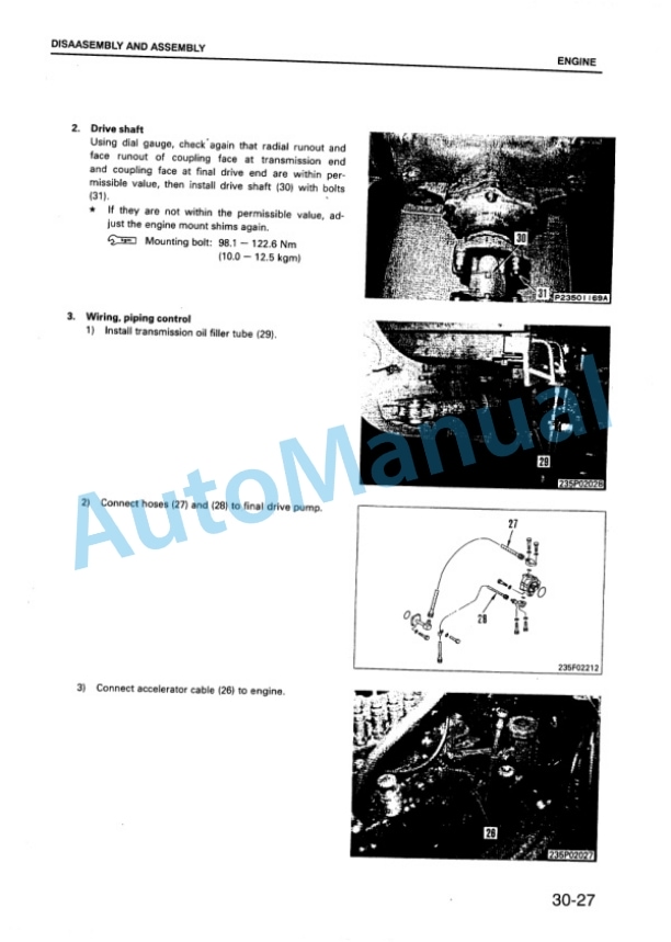
- 5.12. ENGINE (INCL. TRANSMISSION)
- 5.13. TRANSMISSION CONTROL VALVE
- 5.13.1. Disassembly
- 5.13.2. Assembly
- 5.14. HYDROSHIFT TRANSMISSION PUMP
- 5.14.1. Removal and Installation
- 5.15. TANDEM AND FINAL DRIVE
- 5.16. PARKING BRAKE CALIPER PADS
- 5.16.1. Removal
- 5.16.2. Installation
- 5.17. AIR TANK
- 5.17.1. Removal and Installation
- 5.18. ALCHOL INJECTOR
- 5.18.1. Filing and draining
- 5.19. HYDRAULIC TANK
- 5.19.1. Removal and Installation
- 5.20. HYDRAULIC CONTROL VALVE
- 5.20.1. Disassembly
- 5.20.2. Assembly
- 5.21. MAIN CONTROL VALVE
- 5.21.1. Disassembly
- 5.21.2. Assembly
- 5.22. CIRCLE ROTATION MOTOR
- 5.22.1. Disassembly
- 5.22.2. Assembly
- 5.23. DRAWBAR SHIFT CYLINDER, BLADE
- 5.24. LIFT CYLINDER, LIFTER GUIDE
- 5.24.1. Removal
- 5.24.2. Installation
- 5.25. ARTICULATE CYLINDER
- 5.25.1. Removal and Installation
- 5.26. REAR MOUNT RIPPER CYLINDER
- 5.26.1. Removal and Installation
- 5.27. HYDRAULIC CYLINDER
- 5.27.1. Disassembly
- 5.27.2. Assembly
- 5.28. CIRCLE ROTATION GEAR AND HYDRAULIC OIL MOTOR
- 5.28.1. Removal and installation
- 5.29. CIRCLE AND DRAWBAR
- 5.29.1. Removal and Installation
- 5.29.2. Disassembly
- 5.29.3. Assembly
- 5.30. REAR MOUNT RIPPER
- 5.30.1. Removal
- 5.30.2. Installation
- 5.31. METHOD FOR LIFTING UP ROPS CAB
- 5.32. INSTALLATION OF ROPS
- 5.33. ROPS CAB
- 5.33.1. Removal
- 5.33.2. installation
- 5.34. ARTICULATE SECTION
- 6. MAINTENANCE STANDARD
- 6.1. HYDROSHIFT transmission and transfer
- 6.2. Transmission pump
- 6.3. Transmission control valve
- 6.4. Transmission solenoid valve
- 6.5. Final drive
- 6.6. Differential lockup pump
- 6.7. Tandem drive
- 6.8. Front axle
- 6.9. Steering cylinder
- 6.10. Disc brake
- 6.11. Parking brake
- 6.12. Spring cylinder
- 6.13. Hydraulic control valve
- 6.14. Hydraulic cylinder
- 6.15. Hydraulic pump
- 6.16. Drawbar and lifter
- 6.17. Blade
- 6.18. Circle rotation gear
- 6.19. Ripper
- 6.20. Frame


Reviews
There are no reviews yet.