
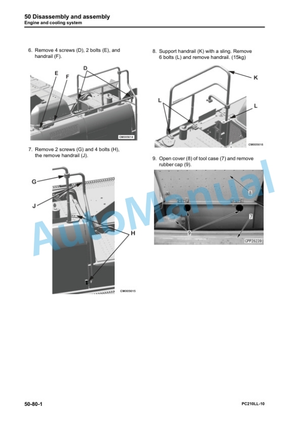
Description
-
Model List:
- PC210LL-10 Hydraulic Excavator
- 1. CEBM029201 PC210LL10 S/N A52001 Up
- 1.1. Index and foreword
- 1.1.1. Index
- 1.1.2. Foreword, safety and general information
- 1.1.2.1. Important safety notice
- 1.1.2.2. How to read the shop manual
- 1.1.2.3. Explanation of terms for maintenance standard
- 1.1.2.4. Handling equipment of fuel system devices
- 1.1.2.5. Handling of intake system parts
- 1.1.2.6. Handling of hydraulic equipment
- 1.1.2.7. Method of disconnecting and connecting of pushpull type coupler
- 1.1.2.8. Handling of electrical equipment
- 1.1.2.9. How to read electric wire code
- 1.1.2.10. Precautions when performing operation
- 1.1.2.11. Practical use of KOMTRAX
- 1.1.2.12. Standard tightening torque table
- 1.1.2.13. List of abbreviation
- 1.1.2.14. Conversion table
- 1.2. Specification
- 1.2.1. Table of contents
- 1.2.2. Specifications
- 1.2.2.1. Specification drawing
- 1.2.2.2. Working range drawings
- 1.2.2.3. Specifications
- 1.2.2.4. Weight table
- 1.2.2.5. Table of fuel, coolant, and lubricants
- 1.3. Structure and function
- 1.3.1. Table of contents
- 1.3.2. Engine and cooling system
- 1.3.2.1. Engine related parts
- 1.3.2.2. KVGT
- 1.3.2.3. EGR system piping drawing
- 1.3.2.4. EGR system circuit diagram
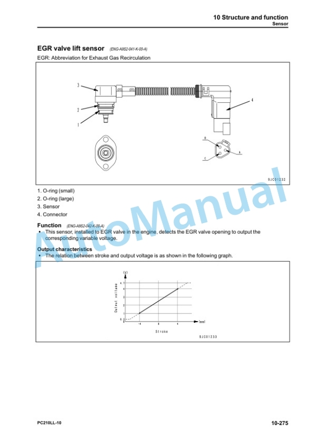
- 1.3.2.5. EGR valve
- 1.3.2.6. EGR cooler
- 1.3.2.7. KCCV layout drawing
- 1.3.2.8. KCCV ventilator
- 1.3.2.9. KDPF
- 1.3.2.10. Cooling system
- 1.3.3. Power train
- 1.3.3.1. Power train system
- 1.3.3.2. Swing circle
- 1.3.3.3. Swing machinery
- 1.3.3.4. Final drive
- 1.3.4. Undercarriage and frame
- 1.3.4.1. Track frame and idler cushion
- 1.3.5. Hydraulic system
- 1.3.5.1. Hydraulic equipment layout drawing
- 1.3.5.2. Valve control
- 1.3.5.3. Hydraulic tank
- 1.3.5.4. Solenoid valve
- 1.3.5.5. Attachment circuit selector valve (for high pressure circuit)
- 1.3.5.6. Attachment circuit selector valve (for low pressure circuit)
- 1.3.5.7. Center swivel joint
- 1.3.5.8. Accumulator
- 1.3.6. Work equipment
- 1.3.6.1. Work equipment
- 1.3.6.2. Work equipment shim
- 1.3.6.3. Bucket play adjustment shim
- 1.3.7. Cab and its attachments
- 1.3.8. Electrical system
- 1.3.8.1. Electrical control system
- 1.3.8.2. Machine monitor system
- 1.3.8.3. KOMTRAX system
- 1.3.8.4. Sensor
- 1.4. Standard value tables
- 1.4.1. Table of contents
- 1.4.2. Standard service value table
- 1.4.2.1. Standard value table for engine
- 1.4.2.2. Standard value table for machine
- 1.4.2.3. Standard value table for electrical system
- 1.5. Testing and adjusting
- 1.5.1. Table of contents
- 1.5.2. General information on testing and adjusting
- 1.5.3. Engine and cooling system
- 1.5.4. Power train
- 1.5.5. Undercarriage and frame
- 1.5.6. Hydraulic system
- 1.5.7. Cab and its attachments
- 1.5.8. Electrical system
- 1.5.9. Pm clinic
- 1.6. Troubleshooting
- 1.6.1. Table of contents
- 1.6.2. General information on troubleshooting
- 1.6.3. Troubleshooting by failure code (Display of code)
- 1.6.4. Troubleshooting of hydraulic and mechanical system (Hmode)
- 1.6.5. Troubleshooting of engine (Smode)
- 1.7. Disassembly and assembly
- 1.7.1. Table of Contents
- 1.7.2. General information on disassembly and assembly
- 1.7.3. Engine and Cooling System
- 1.7.4. Power train
- 1.7.5. Undercarriage and frame
- 1.7.6. Hydraulic system
- 1.7.7. Work equipment
- 1.7.8. Cab and its attachments
- 1.7.9. Electrical system
- 1.8. Maintenance standard
- 1.8.1. Table of contents
- 1.8.2. Engine and cooling system
- 1.8.3. Power train
- 1.8.4. Undercarriage and frame
- 1.8.5. Hydraulic system
- 1.8.6. Work equipment
- 1.9. Appendix
- 1.9.1. Table of contents
- 1.9.2. Air conditioner components
- 1.10. Diagrams and drawings
- 1.10.1. Table of contents
- 1.10.2. Hydraulic circuit diagram
- 1.10.2.1. Symbols in hydraulic circuit diagram
- 1.10.2.2. Hydraulic circuit diagram
- 1.10.3. Electric circuit diagram
- 1.10.3.1. Symbols in electric circuit diagram
- 1.10.3.2. Electric circuit diagram
- 1.10.3.3. Electric circuit diagram for air conditioner unit
- 1.10.4. Connector List and Stereogram
- 1.10.4.1. Chassis
- 1.10.4.2. Operators Compartment
- 1.10.4.4. Engine Compartment


Reviews
There are no reviews yet.