

Description
-
Model List:
- PC4000E-6 Hydraulic Mining Shovel
- 1. Foreword
- 1.1. Introduction
- 1.2. Safety Instructions
- 2. Specification
- 2.1. Specification PC4000
- 3. Structure, Function
- 3.1. INTRODUCTION
- 3.1.1. I Contents of the Binder
- 3.1.2. II Foreword
- 3.1.3. III Explanation of Abbrevations
- 3.2. II SAFETY
- 3.3. III. SPECIFICATIONS
- 3.3.1. III.I Lifting Gears
- 3.3.2. III.II Standard Tightening Torque Chart
- 3.3.3. III.III Conversion Table
- 3.3.4. III.IV General Specifications
- 3.4. MAIN ASSEMBLY GROUPS
- 3.4.1. General Layout
- 3.4.2. Superstructure
- 3.4.3. Machine House
- 3.4.4. Hydraulic Oil Reservoir
- 3.4.5. Hydraulic Oil Cooler
- 3.4.6. Fuel Tank
- 3.4.7. Counterweight
- 3.4.8. Cab Support
- 3.4.9. Operators Cab
- 3.4.10. Control Blocks
- 3.4.11. Swing Gears
- 3.4.12. Undercarriage
- 3.4.13. Backhoe Attachment (BHA)
- 3.4.14. Front Shovel Attachment (FSA)
- 3.5. DRIVE
- 3.5.1. Prime Drive Assembly
- 3.5.2. Engine and PTO Mounts
- 3.5.3. Fan Drive and Radiator Assembly
- 3.5.4. Pump Distributor Gearbox (PTO)
- 3.5.5. Geislinger Coupling
- 3.5.6. Air Filter
- 3.6. HYDRAULIC OIL TANK
- 3.6.1. General Layout
- 3.6.2. Main Oil Tank, Location of Electric Equipment.
- 3.6.3. Suction Oil Reservoir with Strainers
- 3.6.4. Return Oil Collector Tube with Strainer
- 3.6.5. Back Pressure Valve
- 3.6.6. Transfer Pump
- 3.6.7. Return and Leak Oil Filter
- 3.6.8. Breather Filter
- 3.7. HYDRAULIC OIL COOLING
- 3.7.1. General
- 3.7.2. Function of the Hydraulic Oil Cooling Circuit
- 3.7.3. Adjustment of the Back Pressure Valve
- 3.7.4. Fan Drive (Two Stage Cooler Fan RPM Control)
- 3.7.5. Adjustment of the Cooler Fan Drive Speed
- 3.8. CONTROLLING
- 3.8.1. General Layout
- 3.8.2. Control and Filter Panel Location of Components
- 3.8.3. Pilot Pressure Supply and Adjustments
- 3.8.4. Function Electro Hydraulic Control SYSTEM
- 3.8.5. Potentiometer Control (Lever, Joy Stick)
- 3.8.6. Potentiometer Control (Pedal)
- 3.8.7. Proportional Amplifier Module, Type A
- 3.8.8. Proportional Amplifier Module, Type B
- 3.8.9. Ramp Time Module
- 3.8.10. Adjustments of Amplifier Modules
- 3.8.11. Adjusting the Ramp Time Module
- 3.9. COMPONENTS
- 3.9.1. Main Control Blocks and High Pressure Filter (FSA)
- 3.9.2. Main Control Blocks and High Pressure Filter (BHA)
- 3.9.3. Distributor Manifold Location of Restrictor Blocks and Anti Cavitation Valves (FSA)
- 3.9.4. Distributor Manifold Location of Restrictor Blocks and Anti Cavitation Valves (BHA)
- 3.9.5. Single Control Blocks (Floating) for Stick and Boom (FSA)
- 3.9.6. Restrictor Block with Pressure Relief Valve
- 3.9.7. Anti cavitation valve block
- 3.9.8. Remote Control Valves
- 3.9.9. Directional Solenoid Valves (Three Positions / 4Ways)
- 3.9.10. Proportional Solenoid Valve
- 3.9.11. High Pressure Filter
- 3.9.12. Control Blocks and Valves
- 3.9.13. Travel Brake Valve
- 3.9.14. Pressure Reducing Valve
- 3.9.15. Directional Solenoid Valves (Two Positions / 4Ways)
- 3.9.16. Pressure Increasing Valve
- 3.9.17. Hydraulic Cylinder
- 3.9.18. Swing Ring
- 3.10. MAIN HYDRAULIC PUMPS AND PUMP REGULATION
- 3.10.1. General
- 3.10.2. Main Pumps
- 3.10.3. Electronic Pump Regulation System
- 3.10.4. Hydraulic Constant Regulation System
- 3.10.5. Determination of the Peak Point (Engine Performance)
- 3.10.6. Engine Speed Sensor (Pick up)
- 3.10.7. Energy Efficiency
- 3.11. OPERATING HYDRAULICS
- 3.11.1. General
- 3.11.2. Hydraulic for the Attachment Cylinder FSA and BHA
- 3.11.3. Hydraulic for the Swing Circuit
- 3.11.4. Hydraulic for the Travel Circuit
- 3.12. HYDRAULIC TRACK TENSIONING SYSTEM
- 3.12.1. General
- 3.12.2. Pressure Increasing Valve
- 3.12.3. Tensioning Cylinder
- 3.12.4. Adjustments / Checks
- 3.12.5. Functional Test
- 3.13. ACCESS LADDER HYDRAULICALLY OPERATED
- 3.13.1. General
- 3.13.2. Function of Hydraulically Operated Access Ladder
- 3.13.3. Adjustments / Checks
- 3.14. CABLE DRUM
- 3.14.1. General
- 3.14.2. Function
- 3.15. HINTS FOR READING THE HYDRAULIC DIAGRAM
- 3.15.1. General
- 3.15.2. Symbolic
- 3.16. HINTS FOR READING THE ELECTRIC CIRCUIT DIAGRAM
- 3.16.1. Designation of electrical components
- 3.16.2. Electric symbols
- 3.16.3. Symbols
- 3.16.4. Drawing Concept
- 3.16.5. Reading a Circuit Diagram
- 3.16.6. Component List
- 3.17. ELECTRONIC CONTROL SYSTEM (ECS)
- 3.17.1. General
- 3.17.2. Specifications for Operators
- 3.17.3. Specifications for Service
- 3.17.4. Wiring of the Main Components
- 3.17.5. General Design of THE PLC
- 3.17.6. How to proceed the Maintenance and Installation
- 3.17.7. Front Connector Arrangement
- 3.17.8. Power Supply
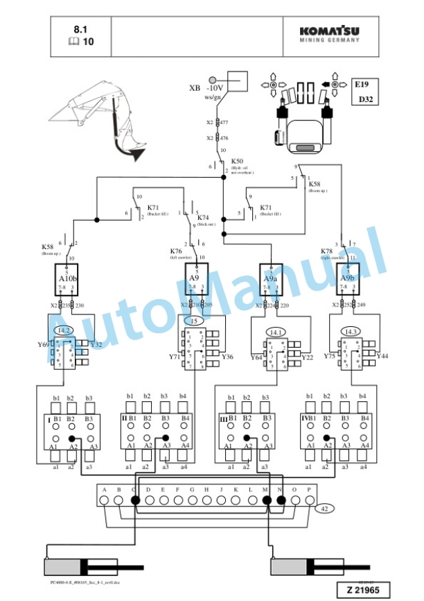
- 3.17.9. Function Explanations with Electrical Diagram
- 3.17.10. Hints for Reading the Functional Flow Charts
- 3.18. AUTOMATIC LUBRICATION SYSTEMS
- 3.18.1. Introduction
- 3.18.2. Central Lubrication System (CLS)
- 3.18.3. Lubrication Pump Station (SLS)
- 3.18.4. Operating and Controlling
- 3.18.5. Adjustments
- 3.18.6. Troubleshooting
- 3.18.7. Commissioning
- 4. Troubleshooting
- 4.1. Safety
- 5. Dissassembly and Assembly
- 5.1. Table of contents
- 5.2. Introduction
- 5.2.1. Contents of this binder
- 5.2.2. Preface
- 5.3. SAFETY
- 5.3.1. SAFETY INFORMATION
- 5.3.2. OVERVIEW
- 5.3.3. SOUND PRESSURE LEVEL IN THE OPERATORS CAB.
- 5.3.4. GENERAL PRECAUTIONS COMMON TO OPERATION ON THE EXCAVATOR
- 5.3.5. PRECAUTION FOR MAINTENANCE
- 5.3.6. ADDITIONAL SAFETY INFORMATION FOR TROUBLESHOOTING AND ADJUSTMENTS
- 5.3.7. SPECIAL SAFETY EQUIPMENT
- 5.4. Superstructure
- 5.4.1. Superstructure / machine house overview
- 5.4.2. Batteries
- 5.4.3. Electric motor
- 5.4.4. Coupling assembly
- 5.4.6. Hydraulics
- 5.4.7. Slew system
- 5.4.8. Lubrication pumps
- 5.4.9. Operators cab
- 5.4.10. Cab base (medium voltage switch cabinet)
- 5.4.11. Access ladder
- 5.4.12. Counterweight
- 5.4.13. Superstructure Lifting
- 5.4.14. High voltage switch cabinet
- 5.4.15. Slip ring unit
- 5.5. Undercarriage
- 5.5.1. Undercarriage overview
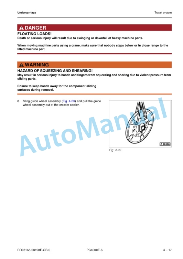
- 5.5.2. Travel system
- 5.5.3. Car body
- 5.5.4. Cable drum (optional)
- 5.5.5. Cable supply
- 5.6. Attachment
- 5.6.1. Backhoe
- 5.6.2. Faceshovel
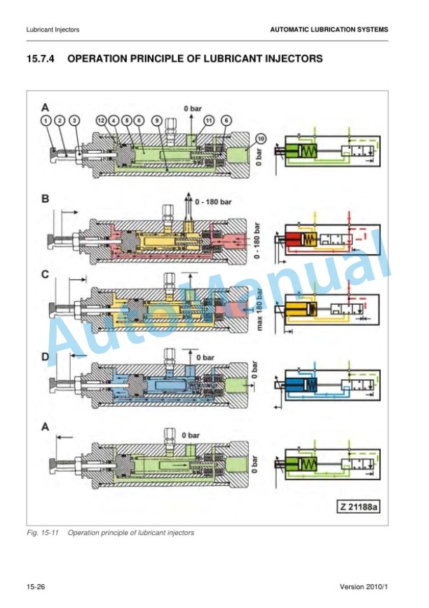
- 5.6.3. Metering valves (grease injectors) at the attachment
- 5.6.4. Cylinder bypass test
- 5.7. Service Information
- 5.7.1. Classification of Voltages for KMG Electric Shovels
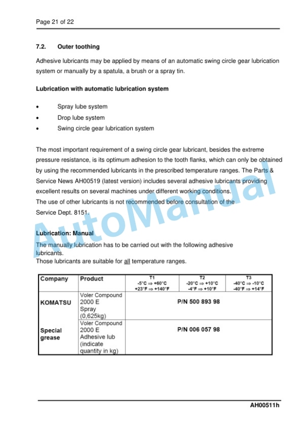
- 5.7.2. Fluids and lubricants
- 5.7.3. Lifting Gears
- 5.7.4. Safety hints for sling accessory
- 5.7.5. Filling capacities
- 5.7.6. Work instructions
- 5.7.7. Weight tables
- 5.7.8. Torque charts according to KOMATSU company standard
- 5.7.9. Blind plugs
- 5.7.10. Conversion table
- 5.7.11. Tools
- 5.8. Tools catalogue
- 5.9. Parts Service News
- 5.9.1. List of the PARTS AND SERVICE NEWS
- 5.10. Suppliers documentation











Reviews
There are no reviews yet.