
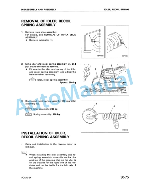
Description
-
Model List:
- PC450-6 Hydraulic Excavator
- PC450LC-6 Hydraulic Excavator
- 1. General
- 1.1. Specification drawings
- 1.2. Specifications
- 1.3. Weight table
- 1.4. Fuel, coolant and lubricants
- 2. Structure and Function
- 2.1. Parts related to engine
- 2.2. Radiator, oil cooler
- 2.3. Power train
- 2.4. Final drive
- 2.5. Swing circle
- 2.6. Swing machinery
- 2.7. Track frame, recoil spring
- 2.8. Track shoe
- 2.9. Hydraulic piping drawing
- 2.10. Hydraulic circuit diagram
- 2.11. Hydraulic tank, hydraulic filter
- 2.12. Hydraulic pump
- 2.13. Control valve
- 2.14. Selfreducing pressure valve
- 2.15. Suction safety valve
- 2.16. CLSS
- 2.17. Swing motor
- 2.18. Center swivel joint
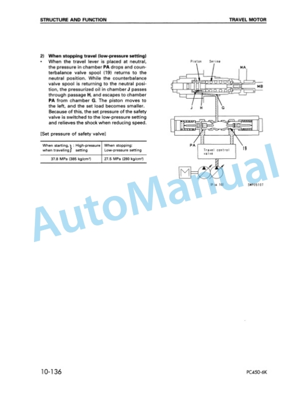
- 2.19. Travel motor
- 2.20. Valve control
- 2.21. Work equipment swing PPC valve
- 2.22. Travel PPC valve
- 2.23. Service PPC valve
- 2.24. PPC safety lock valve
- 2.25. PPC accumulator
- 2.26. PPC shuttle valve, travel junction valve
- 2.27. LSEPC valve
- 2.28. Solenoid valve
- 2.29. Boom safety valve
- 2.30. Overload warning device
- 2.31. Work equipment
- 2.32. Air conditioner
- 2.33. Actual electric wiring diagram
- 2.34. Electric circuit diagram
- 2.35. Engine control
- 2.36. Electronic control system
- 2.37. Machine monitor system
- 2.38. Breaker mode hydraulic performance
- 3. Testing and Adjusting
- 3.1. Standard value table
- 3.1.1. Standard value table for engine related parts
- 3.1.2. Standard value table for chassis related parts
- 3.1.3. Standard value table for electrical parts
- 3.2. Testing and adjusting
- 3.2.1. Tools for testing, adjusting, and troubleshooting
- 3.2.2. Measuring engine speed
- 3.2.3. Measuring exhaust color
- 3.2.4. Adjusting valve clearance
- 3.2.5. Measuring compression pressure
- 3.2.6. Measuring blowby pressure
- 3.2.7. Testing and adjusting fuel injection timing
- 3.2.8. Measuring engine oil pressure
- 3.2.9. Testing and adjusting fan belt tension
- 3.2.10. Testing and adjusting belt tension for air conditioner compressor
- 3.2.11. Adjusting engine speed sensor
- 3.2.12. Measuring air supply pressure (boost pressure)
- 3.2.13. Testing and adjusting governor motor lever stroke
- 3.2.14. Testing and adjusting hydraulic pressure in work equipment, swing, travel circuit
- 3.2.15. Testing and adjusting TVC valve output pressure (servo piston input pressure)
- 3.2.16. Testing and adjusting LS valve output pressure (servo piston input pressure) and LS differential pressure
- 3.2.17. Testing control circuit oil pressure (oil pressure when selfpressure is reduced)
- 3.2.18. Testing solenoid valve output pressure
- 3.2.19. Measuring PPC valve output pressure and testing PPC shuttle valve
- 3.2.20. Adjusting work equipment, swing PPC valve
- 3.2.21. Testing travel deviation
- 3.2.22. Testing locations causing hydraulic drift of work equipment
- 3.2.23. Measuring oil leakage
- 3.2.24. Releasing remaining pressure in hydraulic circuit
- 3.2.25. Testing clearance of swing circle bearing
- 3.2.26. Testing wear of sprocket
- 3.2.27. Testing and adjusting track shoe tension
- 3.2.28. Bleeding air
- 3.3. Troubleshooting
- 3.3.1. Points to remember when troubleshooting
- 3.3.2. Sequence of events in troubleshooting
- 3.3.3. Points to remember when carrying out maintenance
- 3.3.4. Checks before troubleshooting
- 3.3.5. Connector types and mounting locations
- 3.3.6. Connector arrangement diagram
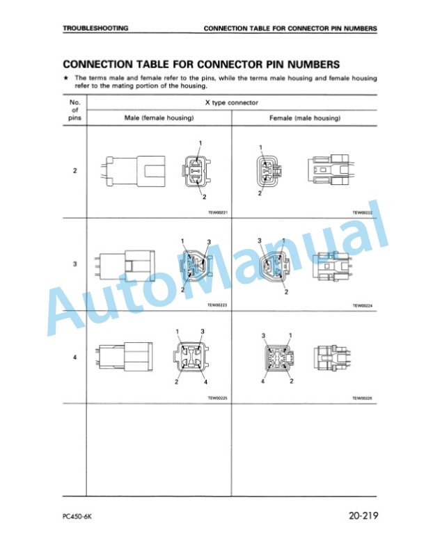
- 3.3.7. Connection table for connector pin numbers
- 3.3.8. Explanation of control mechanism of electrical system
- 3.3.9. Display method of special functions of monitor panel
- 3.3.10. Method of using judgement table
- 3.3.11. Method of using troubleshooting charts
- 3.3.12. Details of troubleshooting and troubleshooting procedure
- 3.3.13. Service code table
- 3.3.14. Troubleshooting of communication abnormality system (N mode)
- 3.3.15. Troubleshooting of governor, pump controller (governor control system) (E mode)
- 3.3.16. Troubleshooting of engine system (S mode)
- 3.3.17. Troubleshooting of governor, pump controller (pump control system) (C mode)
- 3.3.18. Troubleshooting of governor, pump controller (input signal system) (F mode)
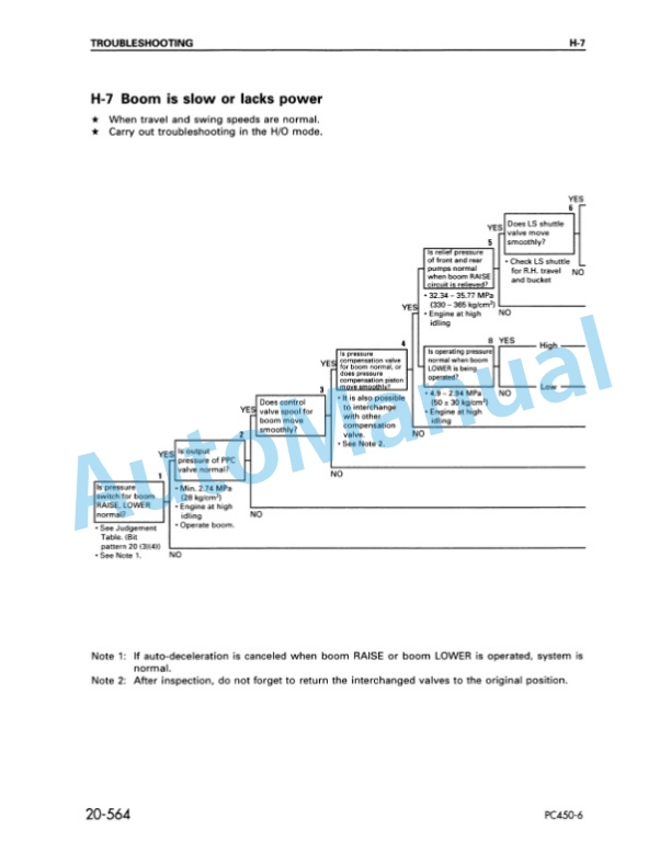
- 3.3.19. Troubleshooting of hydraulic, mechanical system (H mode)
- 3.3.20. Troubleshooting of machine monitor system (M mode)
- 4. Disassembly and Assembly
- 4.1. Method of using manual
- 4.2. Precautions when carrying out operation
- 4.3. Special tool list
- 5. Maintenance Standard
- 6. Others






Reviews
There are no reviews yet.