
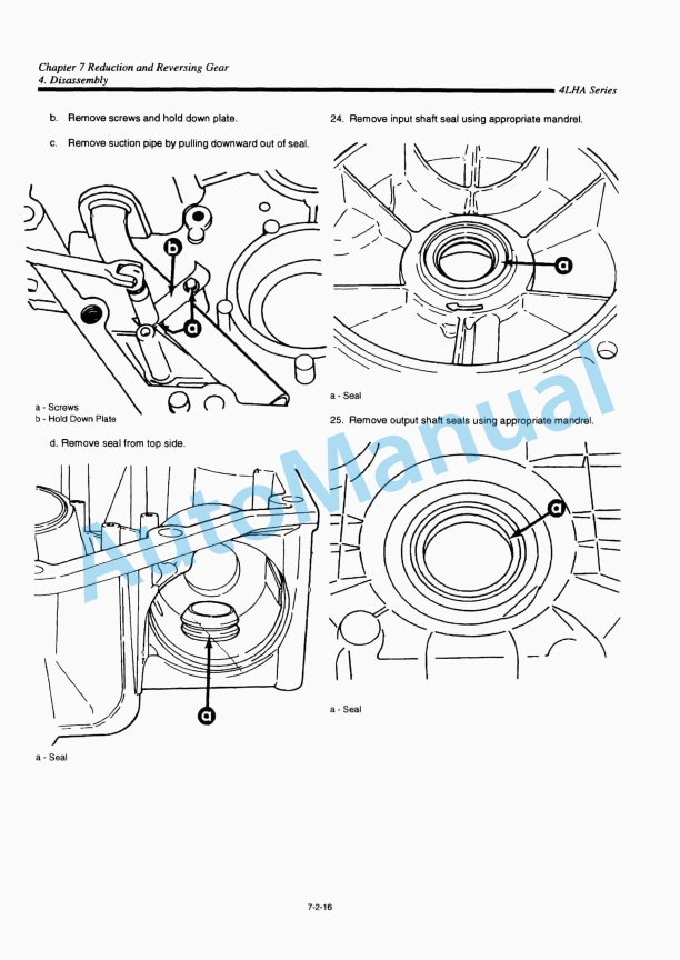
Description
-
Model List:
- 4LHA-STE, 4LHA-STZE, 4LHA-STP, 4LHA-STZP, 4LHA-DTE, 4LHA-DTZE, 4LHA-DTP, 4LHA-DTZP, 4LHA-HTE, 4LHA-HTZE, 4LHA-HTP, 4LHA-HTZP
- 1. FOREWORD
- 2. CHAPTER 0 FOR SAFETY
- 2.1. For Safe Servicing
- 2.2. Precaution For Safe Servicing
- 2.2.1. (A)Service Shop (Place)
- 2.2.2. (B)Working Wear
- 2.2.3. (C)Tools to be Used
- 2.2.4. (D)Use of Genuine Parts, Oil and Grease
- 2.2.5. (E)Bolt and Nut Tightening Torque
- 2.2.6. (F)Electrical Parts
- 2.2.7. (G)Waste treatment
- 2.2.8. (H)Handling the Product
- 2.3. Location of Product Safety Labels
- 3. CHAPTER 1 GENERAL
- 3.1. Exterior Views
- 3.2. Specifications
- 3.3. Service Standards
- 3.4. Performance Curve
- 3.5. Dimensions
- 3.6. Piping Diagrams
- 3.7. Electrical Diagrams
- 4. CHAPTER 2 BASIC ENGINE
- 4.1. Disassembly and Reassembly Tools
- 4.2. Cylinder Block
- 4.3. Cylinder Liners
- 4.4. Cylinder Head
- 4.5. Piston and Piston Pins
- 4.6. Connecting Rod
- 4.7. Crankshaft and Main Bearing
- 4.8. Camshaft and Tappets
- 4.9. Timing Gear
- 4.10. Flywheel
- 5. CHAPTER 3 FUEL INJECTION EQUIPMENT
- 5.1. DISTRIBUTOR TYPE
- 5.1.1. Fuel Supply System
- 5.1.2. Bleeding and Checking Injection Timing
- 5.1.3. Fuel Injection Pump Outline
- 5.1.4. Fuel System
- 5.1.5. Injection Pump Construction and Operation
- 5.1.6. Governing Mechanism
- 5.1.7. Timer Construction and Operation
- 5.1.8. Magnet Valve
- 5.1.9. Pump Reassembly, Adjustment and Inspection
- 5.1.10. Test Bench Adjustment of VE Pump
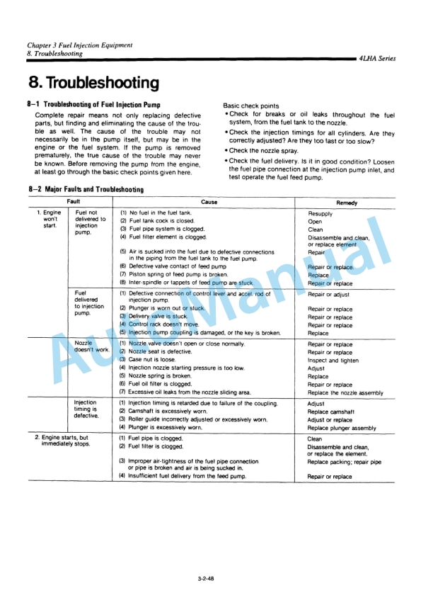
- 5.1.11. Troubleshooting
- 5.1.12. Fuel Injection Nozzle
- 5.1.13. Fuel Filter
- 5.2. YPES-AL TYPE
- 5.2.1. Fuel Supply System
- 5.2.2. Disassembly, Reassembly and Inspection of Governor
- 5.2.3. Disassembly, Reassembly and Inspection of Fuel Injection Pump
- 5.2.4. Adjustment of Fuel Injection Pump and Governor
- 5.2.5. Automatic Advancing Timer
- 5.2.6. Fuel Feed Pump
- 5.2.7. Fuel Injection Nozzle
- 5.2.8. Troubleshooting
- 5.2.9. Tools
- 5.2.10. Fuel Injection Pump Specifications
- 5.2.11. Service Data
- 6. CHAPTER 4 INTAKE AND EXHAUST SYSTEM
- 6.1. Intake and Exhaust System
- 6.2. Intake Silencer
- 6.3. Intake Manifold
- 6.4. Turbocharger
- 6.5. Mixing Elbow
- 6.6. Breather
- 7. CHAPTER 5 LUBRICATION SYSTEM
- 7.1. Lubrication System
- 7.2. Lube Oil Pump
- 7.3. Lube Oil Filter
- 7.4. Oil Pressure Control Valve
- 7.5. Lube Oil Cooler
- 7.6. Piston Cooling Nozzle
- 7.7. Rotary Waste Oil Pump (Optional)
- 8. CHAPTER 6 COOLING WATER SYSTEM
- 8.1. Cooling Water System
- 8.2. Sea Water Pump
- 8.3. Fresh Water Pump
- 8.4. Heat Exchanger
- 8.5. Pressure Cap and Sub Tank
- 8.6. Thermostat
- 8.7. Kingston Cock (Optional)
- 8.8. Sea Water Filter (Optional)
- 8.9. Bilge Pump and Bilge Strainer (Optional)
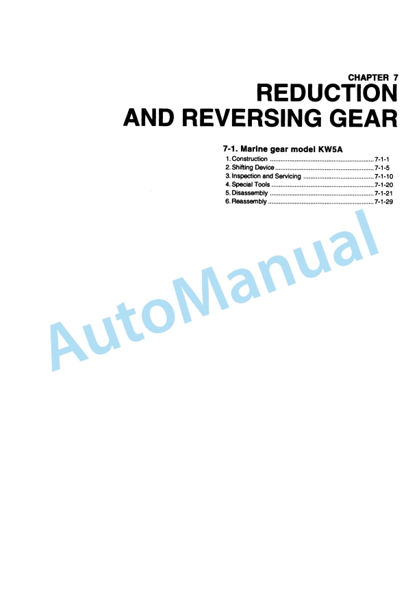
- 9. CHAPTER 7 REDUCTION AND REVERSING GEAR
- 9.1. Marine gear model KM5A
- 9.1.1. Construction
- 9.1.2. Shifting Device
- 9.1.3. Inspection and Servicing
- 9.1.4. Special Tools
- 9.1.5. Disassembly
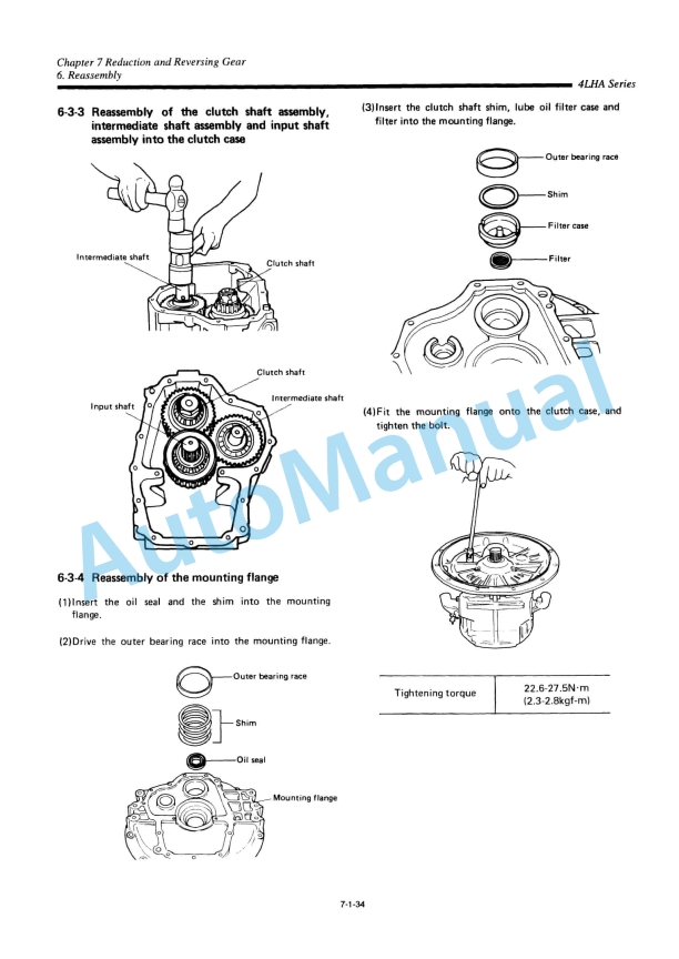
- 9.1.6. Reassembly
- 9.2. Marine gear model HSW630A1
- 9.2.1. Construction
- 9.2.2. Shifting Device
- 9.2.3. Inspection and Servicing
- 9.2.4. Disassembly
- 9.2.5. Reassembly
- 10. CHAPTER 8 REMOTE CONTROL (OPTIONAL)
- 10.1. Remote Control System
- 10.2. Remote Control Installation
- 10.3. Remote Control Inspection
- 10.4. Remote Control Adjustment
- 11. CHAPTER 9 ELECTRICAL SYSTEM
- 11.1. System Diagram
- 11.2. Battery
- 11.3. Starter Motor
- 11.4. Alternator
- 11.5. Instrument Panel
- 11.6. Warning Devices
- 11.7. Tachometer
- 12. COLOPHON
- 13. BACK COVER

,%202GM20(F)(C),%203GM30(F)(C),%203HM35(F)(C)%20Engine%20Service%20Manual&url=https://pdfrepairmanual.com/docs/yanmar-1gm10c-2gm20fc-3gm30fc-3hm35fc-engine-service-manual/&media=https://pdfrepairmanual.com/wp-content/uploads/2026/01/yanmar-1gm10c-2gm20fc-3gm30fc-3hm35fc-engine-service-manual-1.jpg)


There are no reviews yet.