Yanmar 6LP-DTE to 6LPA-STZP Marine Diesel Engine Service Manual
$30.00
- Type Of Manual: Service Manual
- Number of Pages: 247
- Size: 10.4MB
- Format: PDF
Description
-
Model List:
- 6LP-DTE, 6LP-DTZE, 6LP-DTZE1, 6LPA-DTP, 6LPA-DTZP, 6LP-STE, 6LP-STZE, 6LP-STZE1, 6LPA-STP, 6LPA-STZP Diesel Engine
- 1. History of Revision
- 2. FOREWORD
- 3. CONTENTS
- 4. For Safe Operation
- 4.1. Warning Symbols
- 4.2. Precautions for Safe Servicing
- 4.3. Location for Product Safety Labels
- 5. General
- 5.1. Specifications
- 5.2. External Views
- 5.3. Piping Diagram
- 5.4. Performance Curves
- 5.5. Front Power Take-Off(PTO)Output
- 5.6. Fuel Oil
- 5.7. Lube Oil
- 5.8. Cooling Water
- 5.9. Location of Senders and Warning Switches
- 6. Engine Overhaul
- 6.1. Cylinder Head
- 6.1.1. Components
- 6.1.2. Removal of Cylinder Head
- 6.1.2.1. Drain the engine cooling water
- 6.1.2.2. Remove the turbocharger
- 6.1.2.3. Remove fresh water tank
- 6.1.2.4. Remove the fuel filter
- 6.1.2.5. Remove the intake manifold and intercooler
- 6.1.2.6. Remove the fuel injection pipe and fuel injection nozzle(For 6LP-DTE series)
- 6.1.2.7. Remove the bonnet
- 6.1.2.8. Remove the semi-circular plug
- 6.1.2.9. Remove the timing belt and pulley
- 6.1.2.10. Remove the camshaft oil seal retainer
- 6.1.2.11. Remove the fuel injection nozzle(6LP-STE series)
- 6.1.2.12. Remove the camshaft(6LP-STE series)
- 6.1.2.13. Remove the cylinder head assy
- 6.1.3. Disassembly of Cylinder Head
- 6.1.3.1. Remove the valve lifter and shim(6LP-DTE series only)
- 6.1.3.2. Remove the valve bridge
- 6.1.3.3. Remove the intake and exhaust valves
- 6.1.4. Inspection and Servicing of Cylinder Head Components
- 6.1.4.1. Clean the piston and cylinder block top surfaces
- 6.1.4.2. Clean the cylinder head
- 6.1.4.3. Inspect the cylinder head
- 6.1.4.4. Clean the intake and exhaust valves
- 6.1.4.5. Inspection of valve stem and valve guide
- 6.1.4.6. Inspect and lap the intake and exhaust valves
- 6.1.4.7. Inspect and clean the valve seat
- 6.1.4.8. Check the valve spring
- 6.1.4.9. Check the valve rocker arm and shaft(For 6LP-STE series only)
- 6.1.4.10. Check the camshaft and bearing
- 6.1.5. Replacement of Oil Seal for Camshaft
- 6.1.6. Assembly of Cylinder Head
- 6.1.6.1. Install the intake and exhaust valves
- 6.1.6.2. Install the valve bridge(6LP-STE series only)
- 6.1.6.3. Install the valve lifter and shim(6LP-DTE series only)
- 6.1.7. Installation of Cylinder Head
- 6.1.7.1. Measure protrusion of piston head for top surface of cylinder block to betermine an appropriate cylinder head gasket
- 6.1.7.2. Set cylinder No.1 at the bottom dead center
- 6.1.7.3. Install the cylinder head
- 6.1.7.4. Install the camshaft
- 6.1.7.5. Install the fuel injection nozzle
- 6.1.7.6. Install the camshaft oil seal retainer
- 6.1.7.7. Install the pulley and timing belt
- 6.1.7.8. Check and adjust the valve clearance
- 6.1.7.9. Install the semi-circular plug
- 6.1.7.10. Install the bonnet
- 6.2. Cylinder Block
- 6.2.1. Components
- 6.2.2. Preparation for Disassembly
- 6.2.2.1. Remove the flywheel
- 6.2.2.2. Install the engine on the engine stand for disassembling it
- 6.2.2.3. Remove the timing belt and pulley
- 6.2.2.4. Remove the cylinder head
- 6.2.2.5. Remove the fresh water pump and sea water pump
- 6.2.2.6. Remove the alternator
- 6.2.2.7. Remove the timing gear
- 6.2.2.8. Remove the fuel injection pump
- 6.2.2.9. Remove the oil pan and timing gear case
- 6.2.2.10. Remove the oil cooler
- 6.2.2.11. Remove the engine mount
- 6.2.3. Disassembly of Cylinder Block
- 6.2.3.1. Remove the rear oil seal case
- 6.2.3.2. Check the connecting rod thrust clearance
- 6.2.3.3. Remove the connecting rod cap and check oil clearance
- 6.2.3.4. Remove the piston and connecting rod assembly
- 6.2.3.5. Inspect the thrust clearance of the crankshaft
- 6.2.3.6. Remove the main bearing cap and inspect the oil clearance
- 6.2.3.7. Remove the crankshaft
- 6.2.3.8. Remove the check valve and oil nozle(for piston cooling)
- 6.2.4. Inspection of Cylinder Block
- 6.2.4.1. Clean the cylinder block
- 6.2.4.2. Measure warpage of the top surface of cylinder block
- 6.2.4.3. Visually check scratches of the cylinder in the vertical direction
- 6.2.4.4. Measure the cylinder bore diameter
- 6.2.4.5. Clean the cylinder ridge
- 6.2.4.6. Inspect the main bearing cap bolt
- 6.2.5. Disassembly of Piston and Connecting Rod
- 6.2.5.1. Check fitting between the piston and piston pin
- 6.2.5.2. Remove the piston ring
- 6.2.5.3. Remove the conecting rod from the piston
- 6.2.6. Inspection of Piston and Connecting Rod
- 6.2.6.1. Clean the piston
- 6.2.6.2. Inspect the piston and piston ring
- 6.2.6.3. Inspect the piston pin fit
- 6.2.6.4. Inspect the connecting rod
- 6.2.7. Inspection and Servicing of Crankshaft
- 6.2.7.1. Measure circle runout of the crankshaft
- 6.2.7.2. Inspect the crank journal and crank pin
- 6.2.8. Replacement of Oil Seal for Crankshaft
- 6.2.8.1. When the rear oil seal case has been removed from the cylinder block
- 6.2.8.2. When the rear oil seal case is installed to the cylinder block
- 6.2.9. Assembly of Piston and Connecting Rod
- 6.2.9.1. Assemble the piston and connecting rod
- 6.2.9.2. Install the piston ring
- 6.2.9.3. Install the crank pin bearing
- 6.2.10. Assembly of Cylinder Block
- 6.2.10.1. Install the oil nozzle and check valve for the piston cooling
- 6.2.10.2. Installl the main bearing
- 6.2.10.3. Place the crankshaft on the cylinder block
- 6.2.10.4. Install the thrust bearing
- 6.2.10.5. Install the main bearing cap
- 6.2.10.6. Inspect the thrust clearance of the crankshaft
- 6.2.10.7. Install the piston and connecting rod assembly
- 6.2.10.8. Install the connecting rod thrust clearance
- 6.2.10.9. Check the connecting rod thrust clearance
- 6.2.10.10. Install the rear oil seal case
- 6.2.11. Next Assembly
- 6.2.11.1. Install the engine mounting bracket
- 6.2.11.2. Install the timing gear case
- 6.2.11.3. Install the oil pan
- 6.2.11.4. Install the real end plate
- 6.2.11.5. Install the flywheel
- 6.2.11.6. Install the flywheel housing by tightening the set bolts
- 6.2.11.7. Upside down the engine and place it on the engine stand
- 6.2.11.8. Install the thermostat
- 6.2.11.9. Install the alternator and bracket assembly
- 6.2.11.10. Install the fresh water pump
- 6.2.11.11. Install the cylinder head
- 6.2.11.12. Install the timing belt and pulley
- 6.2.11.13. Remove the engine from the engine stand
- 6.2.11.14. Install the turbocharger oil pipe
- 6.2.11.15. Install the oil cooler assembly,oil dipstick and guide
- 6.2.11.16. Install the sender units and warning switches
- 6.2.11.17. Install the fuel injection pump
- 6.2.11.18. Install the sea water pump
- 6.2.11.19. Install the lube oil filter
- 6.3. Timing Belt
- 6.3.1. Components
- 6.3.2. Removal of Timing Belt
- 6.3.2.1. Remove the timing belt cover
- 6.3.2.2. Set the No.1 cylinder at the bottom dead center(BDC)
- 6.3.2.3. Remove the timing belt
- 6.3.2.4. Remove the idler pulley
- 6.3.2.5. Remove No.2 camshaft timing pulley
- 6.3.2.6. Remove the bonnet
- 6.3.2.7. Remove No.1 camshaft timing pulley
- 6.3.3. Checking of Timing Belt
- 6.3.3.1. Checking the timing belt
- 6.3.3.2. Inspect the idler pulley
- 6.3.3.3. Inspect the tension spring and tensioner
- 6.3.4. Installation of Timing Belt
- 6.3.4.1. Install No.1 camshaft timing pulley
- 6.3.4.2. Install the bonnet
- 6.3.4.3. Install No.2 camshaft timing pulley
- 6.3.4.4. Install the idler pulley
- 6.3.4.5. Set the No.1 cylinder to the bottom dead center(BDC)
- 6.3.4.6. Install the timing belt
- 6.3.4.7. Install the tension spring(6LP-DTE series)
- 6.3.4.8. Install the timing belt tensioner(6LP-STE series)
- 6.3.4.9. Inspect the valve timing
- 6.3.4.10. Install the timing belt cover
- 6.4. Timing Gear
- 6.4.1. Components
- 6.4.2. Removal of Timing Gear
- 6.4.2.1. Remove the V-belt for driving the fresh water pump and alternator
- 6.4.2.2. Loosen the crankshaft pulley
- 6.4.2.3. Remove the timing belt and pulley
- 6.4.2.4. Remove the camshaft oil seal retainer
- 6.4.2.5. Remove the crankshaft pulley
- 6.4.2.6. Remove the alternator adjusting bar
- 6.4.2.7. Remove the timing gear cover
- 6.4.2.8. Remove the oil pump drive shaft gear
- 6.4.2.9. Inspect thrust clearance of the idler gear
- 6.4.2.10. Remove the idler gear
- 6.4.2.11. Remove the fuel injection pump drive gear
- 6.4.2.12. Remove the crankshaft timing gear
- 6.4.3. Inspection of Timing Gear
- 6.4.3.1. Check the idler gear
- 6.4.3.2. Check the fuel injection pump drive gear bearing
- 6.4.3.3. Replace the fuel injection pump drive gear bearing,as needed
- 6.4.3.4. Inspect backlash of the timing gear
- 6.4.4. Replacement of Crankshaft Front Oil Seal
- 6.4.4.1. Replace the crankshaft front oil seal
- 6.4.5. Replacement of Fuel Injection Pump Drive Gear Oil Seal
- 6.4.5.1. Replace the fuel injection pump drive gear oil seal
- 6.4.6. Installation of Timing Gear
- 6.4.6.1. Install the crankshaft timing gear
- 6.4.6.2. Install the fuel injection pump drive gear
- 6.4.6.3. Install the idler gear
- 6.4.6.4. Install the oil pump drive shaft gear
- 6.4.6.5. Install the timing gear cover
- 6.4.6.6. Install the alternator adjusting bar
- 6.4.6.7. Install the crankshaft pulley
- 6.4.6.8. Install camshaft oil seal retainer
- 6.4.6.9. Install timing pulleys and timing belt
- 6.4.6.10. Tighten crankshaft pulley bolt
- 6.4.6.11. Install the V-belt for driving the fresh water pump and alternator
- 6.5. Valve Clearance Inspection and Adjustment
- 6.5.1. Inspection of Valve Clearance
- 6.5.1.1. Remove the bonnet
- 6.5.1.2. Set No.1 cylinder to the top dead center(TDC)
- 6.5.1.3. Inspect the valve clearance
- 6.5.2. Adjustment of Valve Clearance
- 6.5.2.1. Adjust the valve clearance
- 6.5.2.2. Install the bonnet
- 6.6. Inspection and Adjustment of Injection Timing
- 6.6.1. Inspection of Injection Timing
- 6.6.1.1. Set the No.1 or No.6 cylinder at the top dead center(TDC)/compression
- 6.6.1.2. Install the plunger stroke measuring tool and dial indicator
- 6.6.1.3. Inspect the engine and check for fuel oil leakage
- 6.6.2. Adjustment of Injection Timing
- 6.6.2.1. Adjust the injection timing
- 6.6.2.2. Tighten union nuts for the fuel injection pipe
- 6.6.2.3. Start the engine and check for fuel oil leakage
- 6.7. Service Specifications
- 6.7.1. Engine Adjusting Standerds
- 6.7.2. Service Standerds
- 6.7.3. Nut and Bolt Tightening Torque
- 6.8. Turbocharger
- 6.8.1. Construction and Function
- 6.8.1.1. Overview of construction and funktion
- 6.8.2. Components(RHE6W Turbocharger)
- 6.8.3. Service Specifications
- 6.8.3.1. Service standards
- 6.8.3.2. Nut and bolt tightening torque
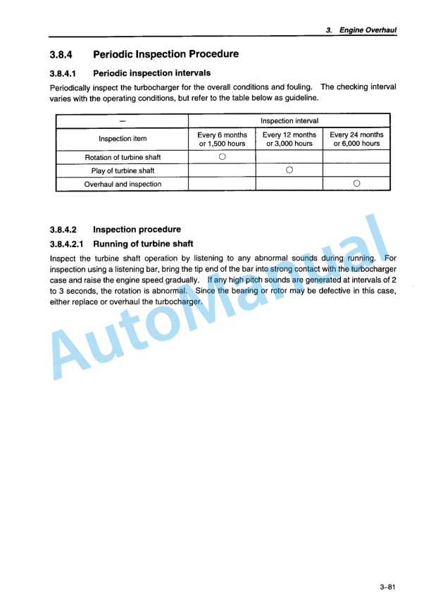
- 6.8.4. Periodic Inspection Procedure
- 6.8.4.1. Periodic inspection intervals
- 6.8.4.2. Inspection procedure
- 6.8.5. Disassembly Procedure
- 6.8.5.1. Preparation for disasembly
- 6.8.5.2. Inspection before disassembly
- 6.8.5.3. Disassembly
- 6.8.6. Cleaning and Checking Procedures
- 6.8.6.1. Cleaning
- 6.8.6.2. Inspection procedure
- 6.8.7. Reassembly Procedure
- 6.8.7.1. Preparation for reassembly
- 6.8.7.2. Reassembly
- 6.8.7.3. Handling after Disassembly and Reassembly
- 6.8.7.4. Troubleshooting
- 6.9. Fuel Filter Replacement
- 6.9.1. Removal of Fuel Filter
- 6.9.1.1. Disconnect the connector of the water alarm switch of the fuel filter
- 6.9.1.2. Drain fuel from the fuel filter
- 6.9.1.3. Fuel filter removal
- 6.9.1.4. Remove the water alarm switch from the fuel filter
- 6.9.2. Installation of Fuel Filter
- 6.9.2.1. Install the water alarm swich to the new fuel filter
- 6.9.2.2. Install the new fuel filter
- 6.9.2.3. Install the water alarm switch connector of the fuel filter
- 6.9.2.4. Fill fuel to the fuel filter
- 6.9.2.5. Start the engine to check for fuel leakage
- 6.10. Fuel Injection Nozzle
- 6.10.1. Components
- 6.10.2. Removal of Fuel Injection Nozzle
- 6.10.3. Testing the Fuel Injection Nozzle
- 6.10.3.1. Leak test
- 6.10.3.2. Testing the spray condition
- 6.10.4. Components of Fuel Injection Nozzle
- 6.10.5. Disassembly of Fuel Injection
- 6.10.5.1. Disassemble the fuel injection nozzle
- 6.10.6. Cleaning and Inspection of Fuel Injection Nozzle
- 6.10.6.1. Cieaning the nozzle
- 6.10.6.2. Inspection of nozzle assembly
- 6.10.7. Adjustment of Fuel Injection Nozzle
- 6.10.7.1. Adjust the needle lift and pre-lift
- 6.10.7.2. For 6LP-DTE series
- 6.10.7.3. For 6LP-STE series
- 6.10.8. Checking No.2 Opening Pressure
- 6.10.9. Adjusting No.1 Opening Pressure
- 6.10.10. Installation of Fuel Injection Nozzle
- 6.10.10.1. Install the fuel injection nozzle
- 6.10.10.2. Install the nozzle holder seal
- 6.10.10.3. Install the fuel injection pipe
- 6.10.10.4. Install the fuel return pipe
- 6.10.10.5. Install the bonnet
- 6.10.10.6. Start the engine and check for fuel leakage
- 6.11. Fuel Injection Pump
- 6.11.1. Removal of Fuel Injection Pump
- 6.11.1.1. Drain cooling water from the engine and disconnect the cooling pipe
- 6.11.1.2. Remove the timing belt
- 6.11.1.3. Remove the No.2 camshaft timing pulley
- 6.11.1.4. Remove the fuel injection pipe
- 6.11.1.5. Disconnect the boost compensator hose
- 6.11.1.6. Remove the fuel injection pump
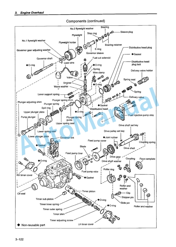
- 6.11.2. Components
- 6.11.3. Installation of Fuel Injection Pump
- 6.11.3.1. Install the fuel injection pump



There are no reviews yet.