Yanmar B95W Wheel Excavator Service Manual
$30.00
- Type Of Manual: Service Manual
- Number of Pages: 913
- Size: 110.3MB
- Format: PDF
Description
- 1. B95W – Cover 01/09/2019
- 1.1. List of Contents
- 1.2. General
- 1.2.1. Foreword / User instructions
- 1.2.2. Safety and accident prevention
- 1.2.3. Description of safety signs
- 1.2.4. Tightening torques of pistons or piston nuts
- 1.2.5. Tightening torques of guide bushings
- 1.2.6. Pictograms
- 1.2.7. Measuring connections
- 1.3. Technical Data
- 1.3.1. Technical data
- 1.3.2. Drift values
- 1.4. Diesel Engine
- 1.4.1. Operating manual TD / TCD 3.6 L4
- 1.4.1.1. Foreword
- 1.4.1.2. Table of contents
- 1.4.1.3. General
- 1.4.1.4. Engine description
- 1.4.1.5. Operation
- 1.4.1.6. Operating media
- 1.4.1.7. Maintenance
- 1.4.1.8. Service and maintenance work
- 1.4.1.9. Transport and storage
- 1.4.1.10. Technical data
- 1.4.2. Workshop Manual TD / TCD 3.6 L4
- 1.4.2.1. Table of contents
- 1.4.2.2. Renewing the crankshaft sealing ring flywheel side)
- 1.4.2.3. Removing and installing the gasket housing
- 1.4.2.4. Removing and installing the transfer line
- 1.4.2.5. Removing and installing the oil pressure regulating valve
- 1.4.2.6. Closing parts
- 1.4.2.7. Oil measuring device
- 1.4.2.8. Removing and installing the lubricating oil pan
- 1.4.2.9. Closing parts
- 1.4.2.10. Drain valve
- 1.4.2.11. Oil filling
- 1.4.2.12. Removing and installing the V-belt pulley / V-ribbed pulley
- 1.4.2.13. Removing and installing the flywheel (Fastening parts)
- 1.4.2.14. Removing and installing the sensor wheel
- 1.4.2.15. V-belt pulley
- 1.4.2.16. Checking the compression pressure (when injectors are removed)
- 1.4.2.17. Removing and installing the cylinder head cover
- 1.4.2.18. Renewing the crankshaft sealing ring (opposite side to flywheel)
- 1.4.2.19. Removing and installing the control valve
- 1.4.2.20. Removing and installing the lubricating oil cooler
- 1.4.2.21. Installing the lubricating oil filter
- 1.4.2.22. Removing and installing the oil suction pipe
- 1.4.2.23. Removing and installing the lubricating oil line (exhaust turbocharger)
- 1.4.2.24. Removing and installing the lubricating oil return line (exhaust turbocharger)
- 1.4.2.25. Lubricating oil line
- 1.4.2.26. Removing and installing the high-pressure pump
- 1.4.2.27. Removing and installing the injector
- 1.4.2.28. Fastening parts
- 1.4.2.29. Fuel pre-filter
- 1.4.2.30. Fuel filter
- 1.4.2.31. Supply pump (Fuel)
- 1.4.2.32. Removing and installing the rail
- 1.4.2.33. Removing and installing the fuel line (injector, rail, high-pressure pump)
- 1.4.2.34. Removing and install the charge air line
- 1.4.2.35. Intake nozzle (exhaust turbocharger)
- 1.4.2.36. Charge air manifold
- 1.4.2.37. Removing and installing the coolant pump
- 1.4.2.38. Drive components
- 1.4.2.39. V-rib belt pulley
- 1.4.2.40. Removing and installing the thermostat
- 1.4.2.41. Checking the thermostat (in the removed state)
- 1.4.2.42. Suction fan
- 1.4.2.43. Pressure fan
- 1.4.2.44. Adapter
- 1.4.2.45. Removing and installing the exhaust line
- 1.4.2.46. Removing and installing the flutter valve
- 1.4.2.47. Removing and installing the cooler
- 1.4.2.48. Removing and installing the exhaust gas return valve
- 1.4.2.49. Removing and installing the exhaust gas return pipe
- 1.4.2.50. Removing and installing the Venturi tube
- 1.4.2.51. Removing and installing the temperature sensor
- 1.4.2.52. Removing and installing the pressure transmitter
- 1.4.2.53. Connection (Crankcase housing, exhaust gas circulation, coolant line)
- 1.4.2.54. Screw plug (Thermostat housing, exhaust gas circulation, coolant line)
- 1.4.2.55. Compensator structure (Exhaust line)
- 1.4.2.56. Line (Crankcase housing, exhaust gas circulation, coolant line)
- 1.4.2.57. Line (Thermostat housing, exhaust gas circulation, coolant line)
- 1.4.2.58. Removing and installing the turbocharger
- 1.4.2.59. Removing and installing the belt tensioner (V-rib belt)
- 1.4.2.60. Removing and installing the console (V-rib belt, level 1)
- 1.4.2.61. Removing and installing the Starter
- 1.4.2.62. Fastening parts
- 1.4.2.63. Generator
- 1.4.2.64. Engine mounting
- 1.4.2.65. Engine mounting
- 1.4.2.66. Engine mounting
- 1.4.2.67. Engine mounting
- 1.4.2.68. Removing and installing the pressure/temperature sensor (charge air)
- 1.4.2.69. Fastening parts
- 1.4.2.70. Fastening parts
- 1.4.2.71. Fastening parts
- 1.4.2.72. Fastening parts
- 1.4.2.73. Removing and installing turning gear/ locking device
- 1.4.2.74. Impulse transmitter (crankshaft)
- 1.4.2.75. Impulse transmitter (camshaft)
- 1.4.2.76. Installing the pressure sensor (oil pressure)
- 1.4.2.77. Removing and installing the connection housing
- 1.4.2.78. Connection housing
- 1.4.2.79. Removing and installing the glow plugs
- 1.4.2.80. Removing and installing the sensor (NOx)
- 1.4.2.81. Removing and installing pressure sensor (exhaust back pressure) SCR (Selective Catalytic Reduction)
- 1.4.2.82. Removing and installing the dosing device SCR Selective Catalytic Reduction)
- 1.4.2.83. Removing and installing temperature transmitter (before diesel oxidation catalyst)
- 1.4.2.84. Removing and installing the compensator (exhaust turbocharger)
- 1.4.2.85. Exhaust back pressure sensor (mixing pipe) SCR (Selective Catalytic Reduction)
- 1.4.2.86. Temperature sensor (air intake temperature, ambient air temperature)
- 1.4.2.87. Coolant line SCR (Selective Catalytic Reduction)
- 1.4.2.88. Catalytic converter DOC (Diesel Oxidation Catalist) / DPF (Diesel Particle Filter)
- 1.4.2.89. Catalytic converter SCR (Selective Catalytic Reduction)
- 1.4.2.90. Supply pump SCR (Selective Catalytic Reduction)
- 1.4.2.91. Console
- 1.4.2.92. Tank SCR (Selective Catalytic Reduction)
- 1.4.2.93. Mixing pipe (Screw connection)
- 1.4.2.94. Removing and installing the coolant compressor
- 1.4.2.95. Fastening parts
- 1.4.2.96. Removing and installing hydraulic pump drive
- 1.4.2.97. Special tools
- 1.4.3. Bleeding the fuel system TCD 3.6 L04
- 1.4.4. AdBlue DEF Installation
- 1.5. Hydraulics
- 1.5.1. 0150 Articulated boom – standard
- 1.5.2. XXXX Articulated boom – standard
- 1.5.3. 0150 Articulated boom – with options
- 1.5.4. XXXX Articulated boom – with options
- 1.5.5. XXXX Articulated boom – with options UNDERCARRIAGE
- 1.5.6. 0484 Articulated boom – with options UPPER CARRIAGE
- 1.5.7. XXXX Articulated boom – with options CONTROL VALVE-1 SX14
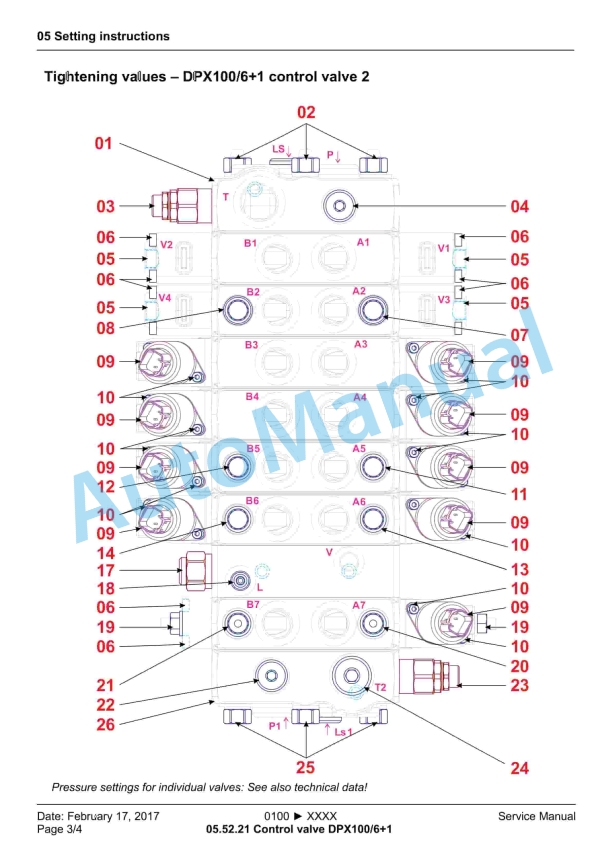
- 1.5.8. XXXX Articulated boom – with options CONTROL VALVE-2 DPX100
- 1.5.9. XXXX Articulated boom – with options UPPER CARRIAGE
- 1.5.10. 0150 Mono boom standard
- 1.5.11. XXXX Mono boom standard
- 1.5.12. 0150 Mono boom – with options
- 1.5.13. XXXX Mono boom – with options
- 1.5.14. 0150 Circular boom – standard
- 1.5.15. XXXX Circular boom – standard
- 1.5.16. 0150 Circular boom – with options
- 1.5.17. XXXX Circular boom – with options
- 1.6. Setting Instructions
- 1.6.1. General setting instructions
- 1.6.2. Hydromatik tightening values
- 1.6.3. Travel hydraulics
- 1.6.4. Control valve SX14
- 1.6.5. Control valve DPX100/61
- 1.6.6. 0150 Pilot control unit
- 1.6.7. XXXX Pilot control unit
- 1.6.8. Working hydraulics
- 1.6.9. Work variable displacement pump
- 1.7. Function Description
- 1.7.1. Pilot control device 4TH6
- 1.7.2. Grip Options – Joystick
- 1.8. Electrics
- 1.8.1. Cable colors
- 1.8.2. Vehicle electric PROJECT TW95_SCRT_0104-_V1.3 from SERIAL-NO. TW09540104 to TW0954XXXX
- 1.8.2.1. Cover sheet
- 1.8.2.2. Schematic circuit diagram
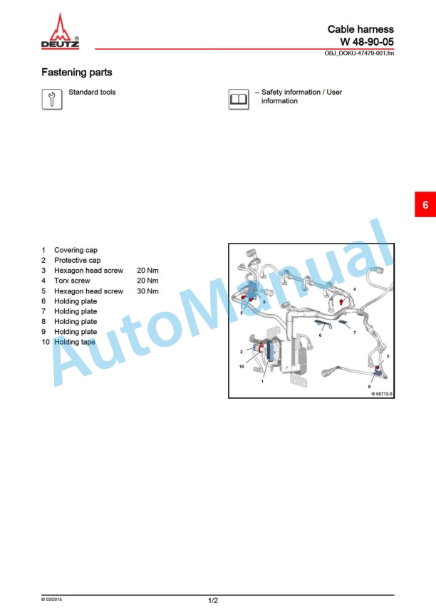
- 1.8.2.3. Cable harness
- 1.8.2.4. overview
- 1.8.3. Monitoring displays
- 1.8.4. Heating and climate controller
- 1.8.5. Relay assignment
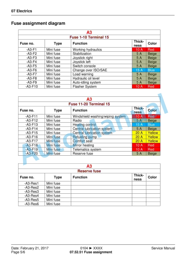
- 1.8.6. Fuse assignment
- 1.8.7. Structural diagram, diesel engine control unit
- 1.8.8. Structural diagram, fan control unit
- 1.8.9. Structural diagram, electrical components
- 1.8.10. Diagnostics and programming connection
- 1.9. Maintenance
- 1.9.1. Specification for fuels, lubricants and coolants
- 1.9.2. Inspection plan
- 1.9.3. Measurement protocol
- 1.10. Operation
- 1.10.1. Keypad operation
- 1.10.2. Instructions for using the combo-tool (display)
- 1.11. Options
- 1.11.1. Pressure setting, front dozer blade
- 1.11.2. Exhaust gas after-treatment system Diesel particle filter (DPF) replacement
- 1.11.3. Auto-idling system
- 1.12. Repair Instructions
- 1.12.1. Fitting hydraulic screw connections
- 1.12.2. Adhesive kit cab windows
- 1.12.3. Tilting the cab
- 1.13. Diagnosis / Tools
- 1.13.1. Special tools – purchased parts
- 1.13.2. ACTIA – Diagnostic Messaging Specification
- 1.13.3. SerDia 2010 – Diagnoses- and Error Codes SPN / FMI
- 1.13.4. Diagnostics and programming port – purchased parts
- 1.14. Home to List of Contents





,%202GM(F)(L),%203GM(D)(F)(L),%203HM(F)(L)%20Engine%20Service%20Manual&url=https://pdfrepairmanual.com/docs/yanmar-1gm10l-2gmfl-3gmdfl-3hmfl-engine-service-manual/&media=https://pdfrepairmanual.com/wp-content/uploads/2026/01/yanmar-1gm10l-2gmfl-3gmdfl-3hmfl-engine-service-manual-1.jpg)


There are no reviews yet.