
Description
-
Model List:
- BY Series 4BY, 6BY
- 1. Table of Contents
- 2. Introduction
- 2.1. Revision History
- 2.1.1. Revision Control Table
- 2.2. Safety Precautions
- 3. General Service Information
- 3.1. Safety Precautions
- 3.2. Engine Outline Drawings
- 3.2.1. Y with KMH40A
- 3.2.2. Y with KMH40A
- 3.3. Engine Piping Diagrams
- 3.4. Location of Nameplates
- 3.4.1. Engine Nameplates (Typical)
- 3.5. Diesel Fuel
- 3.5.1. Diesel Fuel Specifications
- 3.5.2. Bleeding the Fuel System
- 3.6. Engine Oil
- 3.6.1. Engine Oil Specifications
- 3.6.2. Acceptable Engine Oil
- 3.6.3. Recommended Marine Gear or Stern Drive Oil
- 3.6.4. Recommended Power Steering Fluid
- 3.7. Engine Coolant
- 3.7.1. Engine Coolant Specifications
- 3.7.2. Acceptable Engine Coolant
- 3.8. Principal Engine Specifications
- 3.9. Tightening Torques for Standard Bolts and Nuts
- 3.9.1. Tightening Fasteners
- 3.9.2. Hexagon Bolts and Nuts
- 3.9.3. Hose Clamps
- 3.10. Prepare Engine for Long-Term Storage
- 3.11. Abbreviations and Symbols
- 3.11.1. Abbreviations
- 3.11.2. Symbols
- 3.12. Unit Conversions
- 3.12.1. Unit Prefixes
- 3.12.2. Units of Length
- 3.12.3. Units of Volume
- 3.12.4. Units of Mass
- 3.12.5. Units of Force
- 3.12.6. Units of Torque
- 3.12.7. Units of Pressure
- 3.12.8. Units of Power
- 3.12.9. Units of Temperature
- 4. Periodic Maintenance
- 4.1. Introduction
- 4.1.1. The Importance of Periodic Maintenance
- 4.1.2. Performing Periodic Maintenance
- 4.1.3. Yanmar Replacement Parts
- 4.1.4. Required EPA Maintenance
- 4.2. EPA Requirements
- 4.2.1. Conditions to Ensure Compliance with EPA Emission Standards
- 4.2.2. Inspection and Maintenance
- 4.3. Periodic Maintenance Schedule
- 4.4. Periodic Maintenance Procedures
- 4.4.1. After Initial 50 Hours of Operation
- 4.4.2. Every 50 Hours of Operation
- 4.4.3. Every 250 Hours of Operation
- 4.4.4. Every 500 Hours of Operation
- 4.4.5. Every 1000 Hours of Operation
- 4.4.6. Every 2000 Hours of Operation
- 4.5. Before You Begin Servicing
- 4.6. Introduction
- 4.7. Specifications
- 4.7.1. General Information
- 4.7.2. Test and Adjustment Specifications
- 4.7.3. Repair Specifications
- 4.8. Special Torque Chart
- 4.9. Special Service Tools
- 4.10. Measuring Instruments
- 4.11. Sealants and Compounds
- 4.12. Tests and Adjustments
- 4.12.1. Test Compression
- 4.13. Cylinder Head
- 4.13.1. Cylinder Head Components
- 4.13.2. General Guidelines
- 4.13.3. Remove and Install Cylinder Head Cover
- 4.13.4. Remove and Install Glow Plugs
- 4.13.5. Remove Cylinder Head
- 4.13.6. Disassemble Cylinder Head
- 4.13.7. Clean Cylinder Head Components
- 4.13.8. Pressure Test the Cylinder Head
- 4.13.9. Inspect Cylinder Head Components
- 4.13.10. Replace Valve Stem Seals
- 4.13.11. Assemble Cylinder Head
- 4.13.12. Determine Cylinder Head Gasket Thickness
- 4.13.13. Install Cylinder Head
- 4.14. Pistons and Cylinders
- 4.14.1. Remove and Disassemble Piston and Connecting Rod
- 4.14.2. Inspect Pistons and Piston Rings
- 4.14.3. Assemble Piston and Connecting Rod
- 4.14.4. Install Piston and Connecting Rod
- 4.15. Flywheel and Flywheel Housing
- 4.15.1. Remove and Install Flywheel Housing
- 4.15.2. Remove and Install Drive Coupling
- 4.15.3. Remove Flywheel
- 4.15.4. Replace Rear Crankshaft Seal
- 4.15.5. Install Flywheel
- 4.16. Camshaft and Timing Gear Train
- 4.16.1. Components
- 4.16.2. Check and Adjust Camshaft Timing
- 4.16.3. Remove and Install Vibration Damper – 4BY
- 4.16.4. Remove and Install Vibration Damper – 6BY
- 4.16.5. Remove Timing Case Cover
- 4.16.6. Remove and Install Timing Chain
- 4.16.7. Install Timing Case Cover
- 4.16.8. Remove and Install Timing Chain Tensioner
- 4.16.9. Remove Camshafts
- 4.16.10. Install Camshafts
- 4.17. Cylinder Block and Crankshaft
- 4.17.1. Components
- 4.17.2. Remove Crankshaft
- 4.17.3. Measure Oil Clearance
- 4.17.4. Inspect Crankshaft
- 4.17.5. Inspect Cylinder Block
- 4.17.6. Install Crankshaft
- 4.17.7. Replace Front Crankshaft Seal
- 4.18. Intake Manifold
- 4.18.1. Install
- 4.19. Exhaust Manifold
- 4.19.1. Install
- 4.20. Attach Engine to Repair Stand
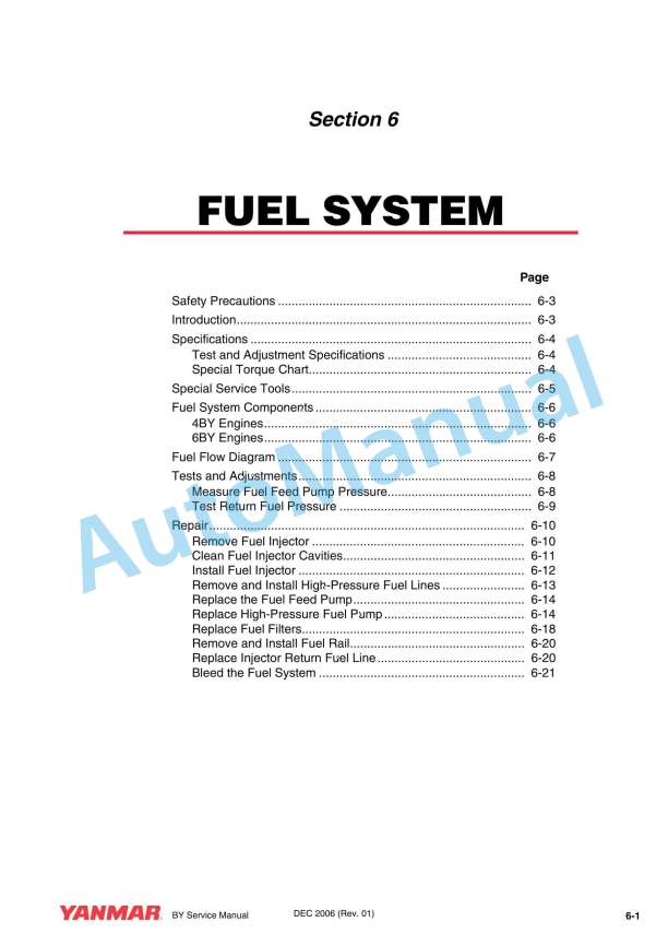
- 5. Fuel System
- 5.1. Safety Precautions
- 5.2. Introduction
- 5.3. Specifications
- 5.3.1. Test and Adjustment Specifications
- 5.3.2. Special Torque Chart
- 5.4. Special Service Tools
- 5.5. Fuel System Components
- 5.5.1. Y Engines
- 5.5.2. Y Engines
- 5.6. Fuel Flow Diagram
- 5.7. Tests and Adjustments
- 5.7.1. Measure Fuel Feed Pump Pressure
- 5.7.2. Test Return Fuel Pressure
- 5.7.3. Remove Fuel Injector
- 5.7.4. Clean Fuel Injector Cavities
- 5.7.5. Install Fuel Injector
- 5.7.6. Remove and Install High-Pressure Fuel Lines
- 5.7.7. Replace the Fuel Feed Pump
- 5.7.8. Replace High-Pressure Fuel Pump
- 5.7.9. Replace Fuel Filters
- 5.7.10. Remove and Install Fuel Rail
- 5.7.11. Replace Injector Return Fuel Line
- 5.7.12. Bleed the Fuel System
- 6. Cooling System
- 6.1. Before You Begin Servicing
- 6.2. Introduction
- 6.3. Specifications
- 6.3.1. Test and Adjustment Specifications
- 6.3.2. Repair Specifications
- 6.3.3. Special Torque Chart
- 6.4. Special Service Tools
- 6.5. Measuring Instruments
- 6.6. Cooling Flow Diagram
- 6.7. Tests and Adjustments
- 6.7.1. Pressure Test Cooling System and Filler Cap
- 6.7.2. Test Thermostat
- 6.7.3. Drain and Refill Seawater Cooling System
- 6.7.4. Check and Replace Zinc Anodes
- 6.7.5. Drain and Fill Closed Cooling System
- 6.7.6. Disconnect and Connect Quick-Connect Fittings
- 6.7.7. Remove and Install Hydraulic Oil Cooler
- 6.7.8. Inspect and Clean Hydraulic Oil Cooler
- 6.7.9. Remove and Install Charge Air Cooler
- 6.7.10. Disassemble and Assemble Charge Air Cooler
- 6.7.11. Remove and Install Heat Exchanger
- 6.7.12. Disassemble and Assemble Heat Exchanger
- 6.7.13. Remove and Install Coolant Pump
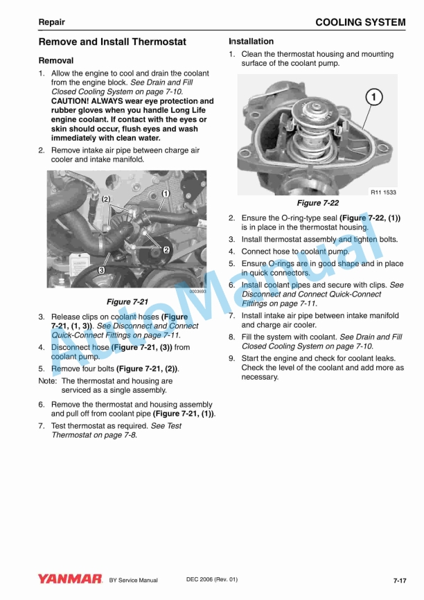
- 6.7.14. Remove and Install Thermostat
- 6.7.15. Seawater Pump
- 7. Lubrication
- 7.1. Introduction
- 7.2. Specifications
- 7.2.1. Test and Adjustment Specifications
- 7.2.2. Special Torque Chart
- 7.3. Special Service Tools
- 7.4. Measuring instruments
- 7.5. Tests and Adjustments
- 7.5.1. Engine Oil Flow
- 7.5.2. Check Engine Oil Pressure
- 7.5.3. Engine Lubrication System Components
- 7.5.4. Change Engine Oil and Replace Engine Oil Filter Element
- 7.5.5. Remove and Install Oil Cooler
- 7.5.6. Remove and Install Oil Filter Housing
- 7.5.7. Remove and Install Oil Sump
- 7.5.8. Oil Pump
- 8. Turbocharger
- 8.1. Introduction
- 8.2. Specifications
- 8.2.1. Test and Adjustment Specifications
- 8.2.2. Special Torque Chart
- 8.3. Special Service Tools
- 8.4. Sealants and compounds
- 8.5. Tests and Adjustments
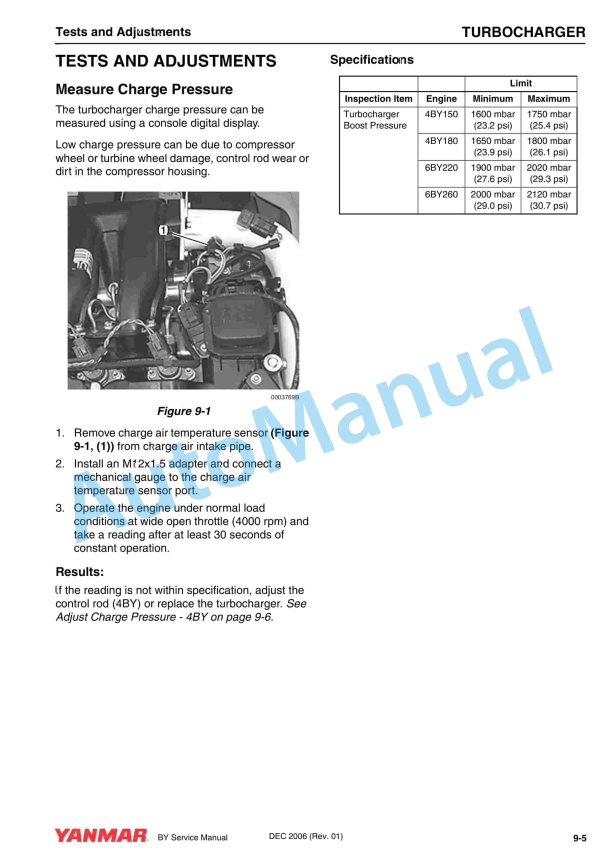
- 8.5.1. Measure Charge Pressure
- 8.5.2. Adjust Charge Pressure – 4BY
- 8.5.3. Remove Turbocharger
- 8.5.4. Install Turbocharger
- 9. Starter Motor
- 9.1. Before You Begin Servicing
- 9.2. Introduction
- 9.3. Starter Motor Specifications
- 9.3.1. General Specifications
- 9.3.2. Special Torque Chart
- 9.4. Starter Motor Troubleshooting
- 9.5. Remove and Install Starter Motor
- 10. Alternator
- 10.1. Before You Begin Servicing
- 10.2. Introduction
- 10.3. Specifications
- 10.3.1. General Specifications
- 10.3.2. Special Torque Chart
- 10.3.3. Replace Alternator Belt
- 10.3.4. Remove and Install Alternator
- 10.3.5. Remove and Install Alternator Belt Tensioner
- 11. Electrical and ECU
- 11.1. Introduction
- 11.2. Specifications
- 11.2.1. Special Torque Chart
- 11.3. Function Description – Engine Management System
- 11.3.1. Component Locations
- 11.3.2. Electrical Panel Connector (X1) Connections
- 11.4. Component Tests
- 11.4.1. Start Relay (K1)
- 11.4.2. Main Relay (K2)
- 11.4.3. Fuel Pump Relay (K3)
- 11.4.4. Oil Pressure Sensor
- 11.4.5. Fuel Injector
- 11.4.6. Engine Coolant Temperature Sensor
- 11.4.7. Fuel Rail Pressure Control Valve
- 11.4.8. Water-in-Fuel Sensor
- 11.4.9. Crankshaft Speed Sensor
- 11.4.10. Glow Plug / Control Unit
- 11.4.11. Fuel Temperature Sensor
- 11.4.12. Fuel Volume Regulator
- 11.4.13. Charge Air Temperature Sensor
- 11.4.14. Charge Air Pressure Sensor
- 11.4.15. Fuel Rail Pressure Sensor
- 11.4.16. Camshaft Speed Sensor
- 11.4.17. Throttle Position Sensor
- 11.4.18. Replace Engine Control Unit (ECU)
- 11.4.19. Replace Coolant Temperature Sensor
- 11.4.20. Replace Charge Air Pressure Sensor
- 11.4.21. Replace Charge Air Temperature Sensor
- 11.4.22. Replace Crankshaft Sensor
- 11.4.23. Replace Camshaft Sensor
- 11.4.24. Replace High-Pressure Fuel Control Valve
- 11.4.25. Replace High-Pressure Fuel Sensor
- 11.4.26. Replace Fuel Temperature Sensor
- 11.4.27. Replace Fuel Volume Regulator
- 11.4.28. Replace Oil Pressure Sensor
- 12. Troubleshooting
- 12.1. Introduction
- 12.2. Engine Faults and Torque Limitations
- 12.2.1. Torque Limitation for Failed Sensors Mode
- 12.2.2. Torque Limitation for Smoke Limitation Mode
- 12.2.3. Torque Limitation for Overheat Protection Mode
- 12.3. Troubleshooting Chart
- 12.3.1. Starting Trouble
- 12.3.2. Exhaust Color
- 12.3.3. Vibration – Drive Disengaged
- 12.3.4. Vibration – Drive Engaged
- 12.3.5. Engine Knocks
- 12.3.6. Low Power Output
- 12.3.7. Engine Overheat
- 12.3.8. Engine Runs Cold
- 12.3.9. Coolant Loss
- 12.3.10. Helm Panel Display
- 12.4. Trouble Codes
- 12.4.1. Working Procedure
- 12.4.2. Diagnostic Trouble Codes
- 12.5. After Troubleshooting or Repair
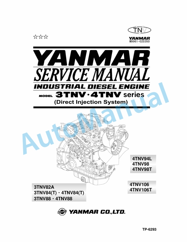


,%202GM(F)(L),%203GM(D)(F)(L),%203HM(F)(L)%20Engine%20Service%20Manual&url=https://pdfrepairmanual.com/docs/yanmar-1gm10l-2gmfl-3gmdfl-3hmfl-engine-service-manual/&media=https://pdfrepairmanual.com/wp-content/uploads/2026/01/yanmar-1gm10l-2gmfl-3gmdfl-3hmfl-engine-service-manual-1.jpg)
There are no reviews yet.