Yanmar SV120 2PB Excavator Service Manual
$30.00
- Type Of Manual: Service Manual
- Number of Pages: 858
- Size: 99.2MB
- Format: PDF
Description
- 1. SV120 2PB – Cover
- 2. List of Contents
- 3. General
- 4. Technical data
- 5. Engine
- 5.1. Operating manual TD – TCD 3.6L4
- 5.1.1. Foreword
- 5.1.2. Table of contents
- 5.1.3. General
- 5.1.4. Engine description
- 5.1.4.1. Engine illustration
- 5.1.4.2. Lubricating oil plan
- 5.1.4.3. Fuel system plan
- 5.1.4.4. Coolant plan
- 5.1.4.5. Exhaust gas recirculation
- 5.1.4.6. Exhaust gas aftertreatment
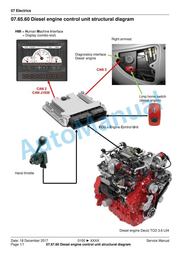
- 5.1.4.7. Electrics/Electronics
- 5.1.5. Operation
- 5.1.5.1. Ambient conditions
- 5.1.5.2. Initial commissioning
- 5.1.5.3. Start process
- 5.1.5.4. Operation monitoring
- 5.1.5.5. Exhaust gas aftertreatment system
- 5.1.5.6. Passive regeneration
- 5.1.5.7. Stopping process
- 5.1.6. Operating media
- 5.1.6.1. Lubricating oil
- 5.1.6.2. Coolant
- 5.1.6.3. SCR reduction agent
- 5.1.7. Maintenance
- 5.1.7.1. Maintenance schedule
- 5.1.8. Service and maintenance work
- 5.1.8.1. Lubricating oil system
- 5.1.8.2. Fuel system
- 5.1.8.3. SCR (Selective Catalytic Reduction)
- 5.1.8.4. Cooling system
- 5.1.8.5. Suction system
- 5.1.8.6. Belt drives
- 5.1.8.7. Engine cleaning
- 5.1.8.8. Electrical system
- 5.1.8.9. Fault table
- 5.1.8.10. Engine management
- 5.1.9. Transport and storage
- 5.1.9.1. Transport
- 5.1.9.2. Engine corrosion protection
- 5.1.10. Technical data
- 5.1.10.1. Engine and setting data
- 5.2. Workshop Manual TD / TCD 3.6 L4
- 5.2.1. Table of contents
- 5.2.1.1. Foreword
- 5.2.1.2. General
- 5.2.1.3. Safety information / User iformation
- 5.2.1.4. Job card overview
- 5.2.1.5. Sorted alphabetically
- 5.2.1.6. Sorted numerically
- 5.2.1.7. Job cards
- 5.2.2. Renewing the crankshaft sealing ring flywheel side)
- 5.2.3. Removing and installing the gasket housing
- 5.2.4. Removing and installing the transfer line
- 5.2.5. Removing and installing the oil pressure regulating valve
- 5.2.6. Closing parts
- 5.2.7. Oil measuring device
- 5.2.8. Removing and installing the lubricating oil pan
- 5.2.9. Closing parts
- 5.2.10. Drain valve
- 5.2.11. Oil filling
- 5.2.12. Removing and installing the V-belt pulley / V-ribbed pulley
- 5.2.13. Removing and installing the flywheel (Fastening parts)
- 5.2.14. Removing and installing the sensor wheel
- 5.2.15. V-belt pulley
- 5.2.16. Checking the compression pressure (when injectors are removed)
- 5.2.17. Removing and installing the cylinder head cover
- 5.2.18. Renewing the crankshaft sealing ring (opposite side to flywheel)
- 5.2.19. Removing and installing the control valve
- 5.2.20. Removing and installing the lubricating oil cooler
- 5.2.21. Installing the lubricating oil filter
- 5.2.22. Removing and installing the oil suction pipe
- 5.2.23. Removing and installing the lubricating oil line (exhaust turbocharger)
- 5.2.24. Removing and installing the lubricating oil return line (exhaust turbocharger)
- 5.2.25. Lubricating oil line
- 5.2.26. Removing and installing the high-pressure pump
- 5.2.27. Removing and installing the injector
- 5.2.28. Fastening parts
- 5.2.29. Fuel pre-filter
- 5.2.30. Fuel filter
- 5.2.31. Supply pump (Fuel)
- 5.2.32. Removing and installing the rail
- 5.2.33. Removing and installing the fuel line (injector, rail, high-pressure pump)
- 5.2.34. Removing and install the charge air line
- 5.2.35. Intake nozzle (exhaust turbocharger)
- 5.2.36. Charge air manifold
- 5.2.37. Removing and installing the coolant pump
- 5.2.38. Drive components
- 5.2.39. V-rib belt pulley
- 5.2.40. Removing and installing the thermostat
- 5.2.41. Checking the thermostat (in the removed state)
- 5.2.42. Suction fan
- 5.2.43. Pressure fan
- 5.2.44. Adapter
- 5.2.45. Removing and installing the exhaust line
- 5.2.46. Removing and installing the flutter valve
- 5.2.47. Removing and installing the cooler
- 5.2.48. Removing and installing the exhaust gas return valve
- 5.2.49. Removing and installing the exhaust gas return pipe
- 5.2.50. Removing and installing the Venturi tube
- 5.2.51. Removing and installing the temperature sensor
- 5.2.52. Removing and installing the pressure transmitter
- 5.2.53. Connection (Crankcase housing, exhaust gas circulation, coolant line)
- 5.2.54. Screw plug (Thermostat housing, exhaust gas circulation, coolant line)
- 5.2.55. Compensator structure (Exhaust line)
- 5.2.56. Line (Crankcase housing, exhaust gas circulation, coolant line)
- 5.2.57. Line (Thermostat housing, exhaust gas circulation, coolant line)
- 5.2.58. Removing and installing the turbocharger
- 5.2.59. Removing and installing the belt tensioner (V-rib belt)
- 5.2.60. Removing and installing the console (V-rib belt, level 1)
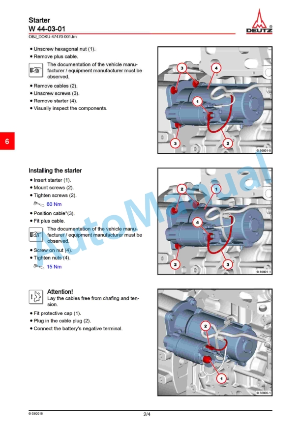
- 5.2.61. Removing and installing the Starter
- 5.2.62. Fastening parts
- 5.2.63. Generator
- 5.2.64. Engine mounting
- 5.2.65. Engine mounting
- 5.2.66. Engine mounting
- 5.2.67. Engine mounting
- 5.2.68. Removing and installing the pressure/temperature sensor (charge air)
- 5.2.69. Fastening parts
- 5.2.70. Fastening parts
- 5.2.71. Fastening parts
- 5.2.72. Fastening parts
- 5.2.73. Removing and installing turning gear/ locking device
- 5.2.74. Impulse transmitter (crankshaft)
- 5.2.75. Impulse transmitter (camshaft)
- 5.2.76. Installing the pressure sensor (oil pressure)
- 5.2.77. Removing and installing the connection housing
- 5.2.78. Connection housing
- 5.2.79. Removing and installing the glow plugs
- 5.2.80. Removing and installing the sensor (NOx)
- 5.2.81. Removing and installing pressure sensor (exhaust back pressure) SCR (Selective Catalytic Reduction)
- 5.2.82. Removing and installing the dosing device SCR Selective Catalytic Reduction)
- 5.2.83. Removing and installing temperature transmitter (before diesel oxidation catalyst)
- 5.2.84. Removing and installing the compensator (exhaust turbocharger)
- 5.2.85. Exhaust back pressure sensor (mixing pipe) SCR (Selective Catalytic Reduction)
- 5.2.86. Temperature sensor (air intake temperature, ambient air temperature)
- 5.2.87. Coolant line SCR (Selective Catalytic Reduction)
- 5.2.88. Catalytic converter DOC (Diesel Oxidation Catalist) / DPF (Diesel Particle Filter)
- 5.2.89. Catalytic converter SCR (Selective Catalytic Reduction)
- 5.2.90. Supply pump SCR (Selective Catalytic Reduction)
- 5.2.91. Console
- 5.2.92. Tank SCR (Selective Catalytic Reduction)
- 5.2.93. Mixing pipe (Screw connection)
- 5.2.94. Removing and installing the coolant compressor
- 5.2.95. Fastening parts
- 5.2.96. Removing and installing hydraulic pump drive
- 5.2.97. Special tools
- 6. Hydraulics
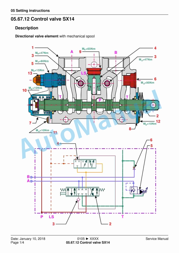
- 7. Setting instructions
- 8. Function description
- 9. Electrics
- 9.1. Instructional film – E3.viewer
- 9.2. E3.viewer – Vehicle electrics Project SCRT_V0.1.2 from Serial-NO. TC12540105 to TC1254XXXX
- 9.3. Vehicle electrics Project SCRT_V0.1.2 from Serial-NO. TC12540105 to TC1254XXXX
- 9.3.1. 6304540002
- 9.3.1.1. 6304540003
- 9.3.1.2. 6304540004
- 9.3.1.3. 6304540005
- 9.3.2. Schematic circuit diagram
- 9.3.2.1. 6304541010
- 9.3.2.2. 6304541011
- 9.3.2.3. 6304541012
- 9.3.2.4. 6304541013
- 9.3.2.5. 6304541014
- 9.3.2.6. 6304541015
- 9.3.2.7. 6304541016
- 9.3.2.8. 6304541017
- 9.3.2.9. 6304541018
- 9.3.2.10. 6304541019
- 9.3.2.11. 6304541020
- 9.3.2.12. 6304541021
- 9.3.2.13. 6304541022
- 9.3.2.14. 6304541023
- 9.3.2.15. 6304541024
- 9.3.2.16. 6304541025
- 9.3.2.17. 6304541026
- 9.3.2.18. 6304541027
- 9.3.2.19. 6304541028
- 9.3.2.20. 6304541029
- 9.3.2.21. 6304541030
- 9.3.2.22. 6304541031
- 9.3.2.23. 6304541032
- 9.3.3. Cable harness
- 9.3.3.1. 1 6304542011
- 9.3.3.2. 1 6304542012
- 9.3.3.3. 1 6304542013
- 9.3.3.4. 2 6304543011
- 9.3.3.5. 2 6304543012
- 9.3.3.6. 3 6293543030
- 9.3.3.7. 2.2 6303740011
- 9.3.3.8. 2.3 6303740121
- 9.3.3.9. 7 6303543020
- 9.3.3.10. 6 6293043040
- 9.3.3.11. 8 6293240031
- 9.3.3.12. 8.1 6291608530
- 9.3.3.13. 1.2 6293042040
- 9.3.3.14. 5 6303544010
- 9.3.3.15. 5 6303544020
- 9.3.3.16. 5 6293044050
- 9.3.3.17. 5 6293044060
- 9.3.3.18. 5 6303544070
- 9.3.3.19. 5 6303544030
- 9.3.4. overview
- 9.3.4.1. 6291540006
- 9.3.4.2. 6304542022
- 9.3.4.3. 6304542023
- 9.3.4.4. 6291542024
- 9.3.4.5. 6291543021
- 9.3.4.6. 6291542025
- 9.3.4.7. 1 6304542021
- 10. Maintenance
- 11. Operation
- 12. Options
- 13. Repair instructions
- 14. Diagnosis / tools
- 15. Home to List of Contents



There are no reviews yet.