
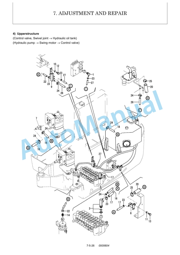
Description
-
Model List:
- SV20 (EP) Excavator
- 1. General Cautions for Maintenance Work
- 1.1. Correct Work
- 1.2. Safety Precautions
- 1.3. Preparations
- 1.4. Cautions for Disassembly and Reassembly
- 1.5. Cautions for Removal and Installation of Hydraulic Equipment
- 1.6. Cautions for Removal and Installation of Hydraulic Piping
- 1.7. Cautions for Handling Seals
- 1.8. Correct Installation of Hydraulic Hose
- 1.9. Specifications of Hydraulic Hose
- 1.10. Air Release of Hydraulic Equipment
- 2. Technical Data
- 2.1. Specifications
- 2.2. Outline Drawing and Working Area
- 2.3. Weight List of Main Parts
- 2.4. Lifting Capacity List
- 3. Service Standards
- 3.1. Machine Performance
- 3.2. Engine
- 3.3. Undercarriage
- 3.3.1. Rubber Crawler Specifications
- 3.3.2. Common Specifications of Steel Rubber Crawlers
- 3.4. Controls
- 3.5. Hydraulic Equipment
- 3.5.1. Hydraulic Cylinders
- 3.6. Implement
- 3.6.1. Front Attachments
- 3.6.2. Blade Moving Device
- 3.6.3. Bucket Teeth
- 3.7. List of Tightening Torque
- 3.7.1. Machine
- 3.7.2. Engine
- 3.7.3. Tightening Torque for General Bolts and Nuts
- 4. Engine
- 4.1. General
- 4.1.1. Engine External Views
- 4.2. Measurement, Inspection and Adjustment
- 4.2.1. Measuring the Compression Pressure
- 4.2.2. Adjusting the Valve Clearance
- 4.2.3. Checking the V-belt Tension
- 4.2.4. Checking the Fuel Injection Valve
- 4.2.5. Checking and adjusting the Fuel Injection Timing
- 4.2.6. Adjusting the Maximum (or Minimum) Idling Speed
- 4.2.7. Checking the Cooling Water System and Radiator for Water Leakage
- 4.2.8. Checking the Sensors
- 4.3. Measurement Procedure, Service Data and Corrective Action
- 4.3.1. Cylinder Head
- 4.3.2. Cylinder Block
- 4.3.3. Valve Rocker Arm
- 4.3.4. Piston and Piston Rings
- 4.3.5. Connecting Rod
- 4.3.6. Cam Shaft
- 4.3.7. Crank Shaft
- 4.3.8. Gears
- 4.3.9. Trochoid Pump
- 4.4. Precautions for Reassembly
- 4.5. Fuel Injection System
- 4.5.1. Introduction
- 4.5.2. Fuel Injection Pump
- 4.5.3. Governor Mechanism
- 4.5.4. Specifications of Fuel Injection Pump
- 4.6. Electrical Equipment
- 4.6.1. Starter Motor
- 4.6.2. Alternator
- 4.6.3. Glow Plug
- 5. Hydraulic System
- 5.1. Outline
- 5.2. Hydraulic Circuit Schematic
- 6. Hydraulic Equipment
- 6.1. Hydraulic Pump
- 6.2. Control Valve
- 6.3. Pilot Valve
- 6.4. Swing Motor
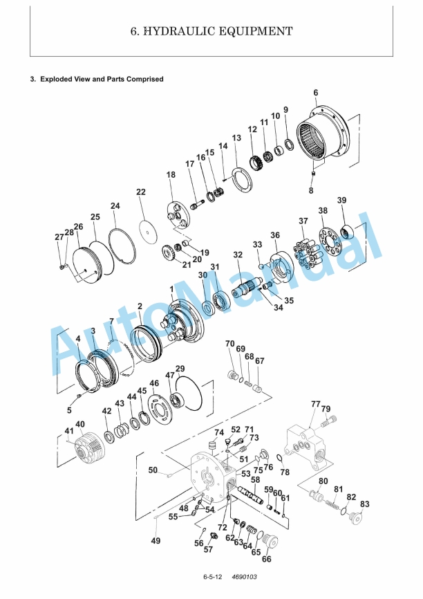
- 6.5. Travel Motor
- 6.5.1. Malfunction of equipment other than motor, counter balance valve and reduction gear.
- 6.5.2. Escape of pressure oil due to excessive wear of motors sliding parts.
- 6.5.3. Malfunction due to breakage of motors sliding parts. (In this case, motor makes an abnormal sound).
- 6.5.4. Relief valve operates due to too much load applied to motor.
- 6.5.5. Specified volume of oil is not being supplied to motor due to failure of hydraulic pump, system relief valve, etc.
- 6.5.6. Specified speed is not obtained due to drop of motors displacement.
- 6.5.7. A large volume of high pressure oil leaks and flows out from drain port due to wear of motors parts, causing a large drop and fluctuation in motor revolutions. The fluctuation is also caused by worn bearing.
- 6.5.8. Breakage of oil seals or O-rings.
- 6.5.9. Plunger is not moved.
- 6.5.10. Plunger does not return.
- 6.5.11. Plunger does not move smoothly.
- 6.5.12. Plunger is quick to return.
- 6.5.13. Plunger does not return.
- 6.5.14. Seat of check valve is defective.
- 6.5.15. Sticking of check valve
- 6.5.16. Spool does not move.
- 6.5.17. Oil leak due to excessive wear of high speed control piston.
- 6.5.18. High speed control piston is not installed.
- 6.5.19. Excessive wear of steel ball.
- 7. Adjustment and Repair
- 7.1. Electric Equipment of Machine
- 7.1.1. Parts Layout of Electrical Equipment
- 7.1.2. Monitor and Alarm Systems
- 7.1.3. Wiring Diagram
- 7.1.4. Circuit Description of Engine Start and Stop, and Battery Charging
- 7.1.5. Removal and Reinstallation of Engine
- 7.1.6. Removal and Reinstallation of Starter Motor
- 7.1.7. Removal and Reinstallation of Fuel Injection Pump
- 7.1.8. Removal and Reinstallation of Fuel Tank
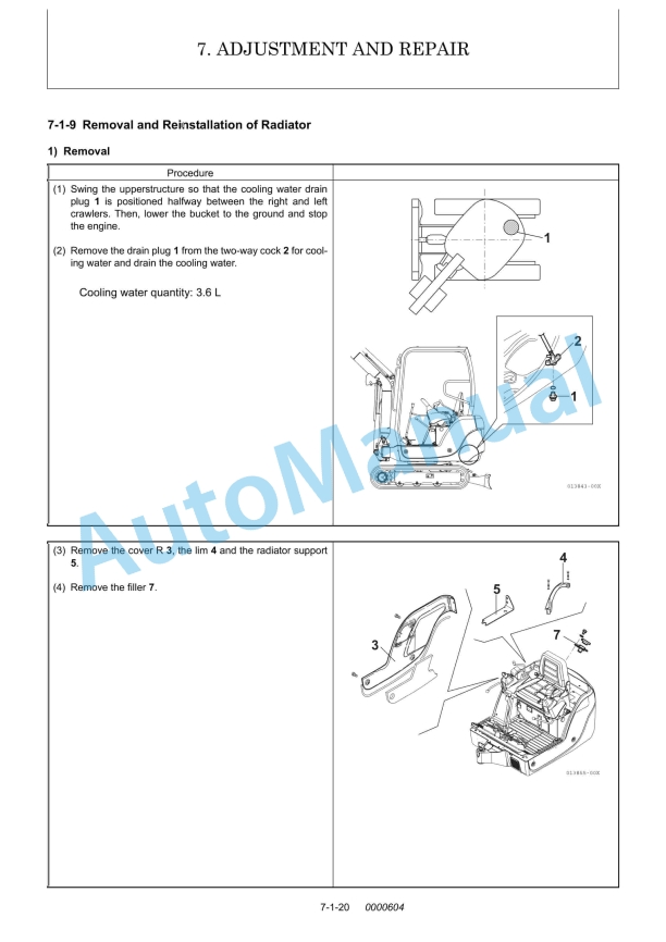
- 7.1.9. Removal and Reinstallation of Radiator
- 7.2. Undercarriage
- 7.2.1. Outline
- 7.2.2. Major Parts
- 7.2.3. Points of Reassembly
- 7.2.4. Removal and Reinstallation of Crawler
- 7.2.5. Disassembly and Reassembly of Idler
- 7.2.6. Disassembly and Reassembly of Track Roller
- 7.3. Controls
- 7.3.1. Control Train
- 7.3.2. Mechanical Control Linkage
- 7.3.3. Adjustment of Travel Levers
- 7.3.4. Adjustment of Boom Swing Pedal
- 7.3.5. Adjustment of Blade Lever (Track Gauge Change Lever)
- 7.3.6. Adjustment of Lock Lever Switch
- 7.3.7. Adjustment of Accelerator Lever
- 7.3.8. Adjustment of P.T.O. Pedal
- 7.4. Swing Bearing
- 7.5. Hydraulic Equipment
- 7.5.1. Removal and Reinstallation of Hydraulic Pump
- 7.5.2. Removal and Reinstallation of Control Valve
- 7.5.3. Removal and Reinstallation of Swing Motor
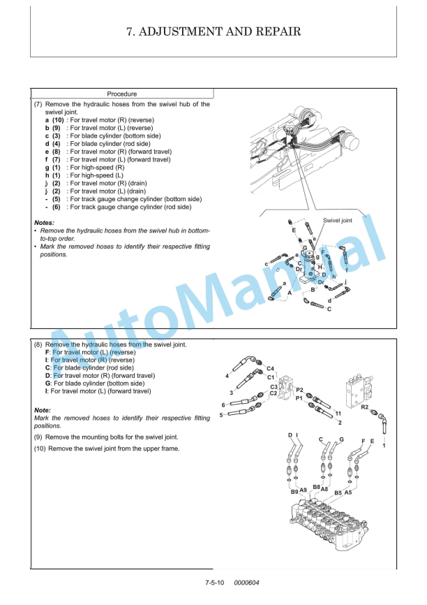
- 7.5.4. Removal and Reinstallation of Swivel Joint
- 7.5.5. Disassembly and Reassembly of Swivel Joint
- 7.5.6. Disassembly and Reassembly of Hydraulic Cylinders
- 7.5.7. Hydraulic Oil Tank
- 7.5.8. Piping Layout
- 7.6. Work Implements
- 7.6.1. Removal and Reinstallation of Work Implements
- 8. Periodic Inspection and Servicing
- 8.1. List of Periodic Inspection and Servicing
- 9. Fuel, Lube Oil and Grease Recommended
- 10. Troubleshooting
- 10.1. Non-Breakdowns
- 10.1.1. Natural Release of Bucket
- 10.1.2. Discontinuous Arm Movement
- 10.1.3. Drifting of Upperstructure on Quick Travel Operation
- 10.1.4. Thermal Shock of Travel Motor
- 10.1.5. Elongation of Boom Swing Cylinder on 75 degrees Swing
- 10.1.6. Telescopic Motion of Boom Swing Cylinder with Lock Lever Set to Lock Position
- 10.1.7. Time Lag on Travel Speed Switching
- 10.1.8. Fluctuation in Oil Level of Hydraulic Oil Tank Due to Temperature Change
- 10.2. Troubleshooting
- 10.2.1. Machine and Engine
- 10.2.2. Electrical Equipment on Panel
- 11. Reference Data
- 11.1. Specifications for Attachment
%20Excavator%20Service%20Manual&url=https://pdfrepairmanual.com/docs/yanmar-sv20-ep-excavator-service-manual/&media=https://pdfrepairmanual.com/wp-content/uploads/2026/01/yanmar-sv20-ep-excavator-service-manual-1.jpg)


,%202GM(F)(L),%203GM(D)(F)(L),%203HM(F)(L)%20Engine%20Service%20Manual&url=https://pdfrepairmanual.com/docs/yanmar-1gm10l-2gmfl-3gmdfl-3hmfl-engine-service-manual/&media=https://pdfrepairmanual.com/wp-content/uploads/2026/01/yanmar-1gm10l-2gmfl-3gmdfl-3hmfl-engine-service-manual-1.jpg)


,%202GM(F)(L),%203GM(D)(F)(L),%203HM(F)(L)%20Marine%20Diesel%20Engine%20Service%20Manual&url=https://pdfrepairmanual.com/docs/yanmar-1gm10l-2gmfl-3gmdfl-3hmfl-marine-diesel-engine-service-manual/&media=https://pdfrepairmanual.com/wp-content/uploads/2026/01/yanmar-1gm10l-2gmfl-3gmdfl-3hmfl-marine-diesel-engine-service-manual-1.jpg)
There are no reviews yet.