
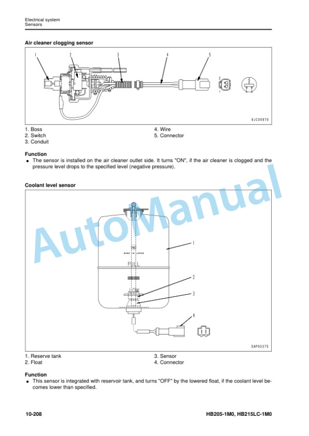
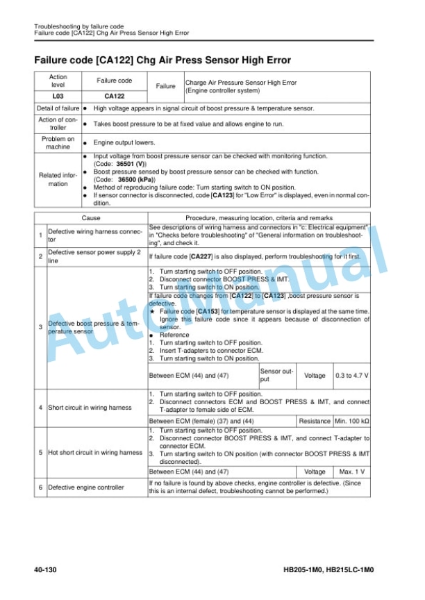
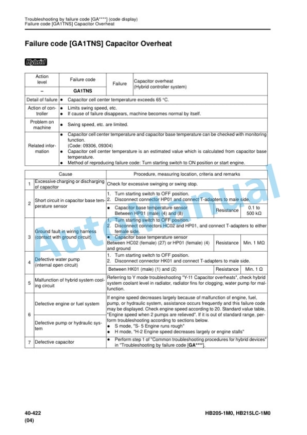
Description
-
Model List:
- HB205-1M0 Hydraulic Excavator
- HB215LC-1M0 Hydraulic Excavator
- 1. Cover
- 2. Notice of revision
- 3. Index and foreword
- 3.1. Table of Contents
- 3.2. Foreword and general information
- 4. Specifications
- 4.1. Contents
- 4.2. Specifications
- 5. Structure and function
- 5.1. Contents
- 5.2. Engine and cooling system
- 5.3. Hybrid relation
- 5.4. Power train system
- 5.5. Undercarriage and frame
- 5.6. Hydraulic system
- 5.7. Work equipment
- 5.8. Electrical system
- 6. Standard value table
- 6.1. Contents
- 6.2. Standard service value table
- 7. Testing and adjusting
- 7.1. Contents
- 7.2. Tools for testing, adjusting and troubleshooting
- 7.3. Engine and cooling system
- 7.4. Swing circle and undercarriage
- 7.5. Hydraulic system
- 7.6. Exterior parts
- 7.7. Hybrid
- 7.8. Electrical system
- 7.9. Pm Clinic
- 8. Troubleshooting
- 8.1. Contents
- 8.2. General information on troubleshooting
- 8.3. Troubleshooting by failure code
- 8.4. Troubleshooting by failure code GA (code display)
- 8.5. Troubleshooting of electrical system (Emode)
- 8.6. Troubleshooting of hydraulic and mechanical system (Hmode)
- 8.7. Troubleshooting of engine (Smode)
- 8.8. Troubleshooting hybrid system (Ymode)
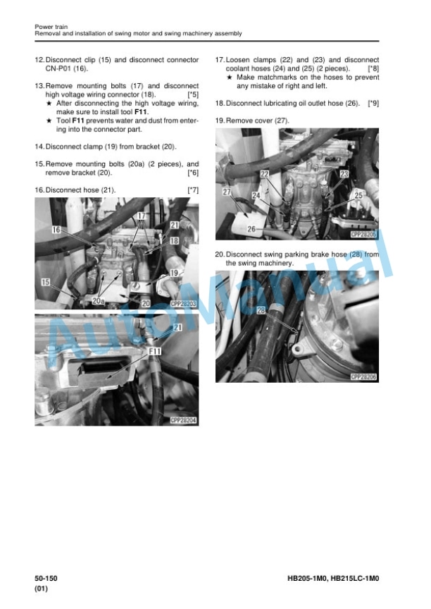
- 9. Disassembly and assembly
- 9.1. Contents
- 9.2. Related information on disassembly and assembly
- 9.3. Engine and cooling system
- 9.4. Hybrid related
- 9.5. Power train
- 9.6. Undercarriage and frame
- 9.7. Hydraulic system
- 9.8. Work equipment
- 9.9. Cab and its attachments
- 9.10. Electrical system
- 10. Maintenance standard
- 10.1. Contents
- 10.2. Engine and cooling system
- 10.3. Power train
- 10.4. Undercarriage and frame
- 10.5. Hydraulic system
- 10.6. Work equipment
- 11. Appendix
- 11.1. Contents
- 11.2. Air conditioner
- 11.3. Precautions for refrigerant
- 11.4. Air conditioner component
- 11.5. Configuration and function of refrigeration cycle
- 11.6. Outline of refrigeration cycle
- 11.7. Air conditioner unit
- 11.8. Air conditioner controller
- 11.9. Compressor
- 11.10. Condenser and Modulator
- 11.11. Sensor
- 11.12. Procedure for testing and troubleshooting
- 11.13. Circuit diagram and arrangement of connector pins
- 11.14. System diagram
- 11.15. Parts and connectors layout
- 11.16. Testing air leakage (duct)
- 11.17. Testing with selfdiagnosis function
- 11.18. Testing vent (mode) changeover
- 11.19. Testing FRESH/RECIRC air changeover
- 11.20. Testing sunlight sensor
- 11.21. Testing (dual) pressure switch for refrigerant
- 11.22. Testing relays
- 11.23. Troubleshooting chart 1
- 11.24. Troubleshooting chart 2
- 11.25. Information in troubleshooting table
- 11.26. Failure code list related to air conditioner
- 11.27. Failure code 879AKA A/C Inner sensor Open Circuit
- 11.28. Failure code 879AKB A/C Inner sensor Short Circuit
- 11.29. Failure code 879BKA A/C Outer sensor Open Circuit
- 11.30. Failure code 879BKB A/C Outer sensor Short Circuit
- 11.31. Failure code 879CKA Ventilating sensor Open Circuit
- 11.32. Failure code 879CKB Ventilating sensor Short Circuit
- 11.33. Failure code 879DKZ Sunlight sensor Open or Short Circuit
- 11.34. Failure code 879EMC Ventilating Damper Abnormality
- 11.35. Failure code 879FMC Air Mix Damper Abnormality
- 11.36. Failure code 879GKX Refrigerant Abnormality
- 11.37. Troubleshooting for power supply and CAN communication system (Air conditioner does not operate)
- 11.38. Troubleshooting for compressor and refrigerant system (Air is not cooled)
- 11.39. Troubleshooting for blower motor system (No air comes out or air flow is abnormal)
- 11.40. Troubleshooting for FRESH/RECIRC air changeover
- 11.41. Troubleshooting with gauge pressure
- 11.42. Connection of service tool
- 11.43. Precautions for disconnecting and connecting air conditioner piping
- 11.44. Handling of compressor oil
- 11.45. Desiccant replacement procedure
- 12. Diagrams and drawings
- 12.1. Contents
- 12.2. Hydraulic circuit diagram
- 12.3. Electrical circuit diagram
- 13. Index


Reviews
There are no reviews yet.