

Description
-
Model List:
- 107E-2 Series Engine
- 1. Cover
- 2. Index and foreword
- 2.1. Index
- 2.2. Foreword, safety and general information
- 2.2.1. Important safety notice
- 2.2.2. How to read the shop manual
- 2.2.3. Explanation of terms for maintenance standard
- 2.2.4. Handling equipment of fuel system devices
- 2.2.5. Handling of intake system parts
- 2.2.6. Handling of hydraulic equipment
- 2.2.7. Method of disconnecting and connecting of pushpull type coupler
- 2.2.8. Handling of electrical equipment
- 2.2.9. How to read electric wire code
- 2.2.10. Precautions when performing operation
- 2.2.11. Standard tightening torque table
- 2.2.12. List of abbreviation
- 2.2.13. Conversion table
- 3. Specification
- 3.1. Table of contents
- 3.2. General information
- 3.2.1. Exhaust gas regulation
- 3.3. Specifications
- 3.3.1. Applicable machines
- 3.3.2. Specifications
- 3.3.3. General view
- 3.3.4. Engine performance curve
- 4. Structure and function
- 4.1. Table of contents
- 4.2. Components layout
- 4.2.1. Components layout drawing (4D107)
- 4.2.2. Components layout drawing (6D107)
- 4.3. Intake and exhaust system parts
- 4.3.1. Intake and exhaust system layout drawing (4D107)
- 4.3.2. Intake and exhaust system layout drawing (6D107)
- 4.3.3. Intake and exhaust system circuit diagram (4D107)
- 4.3.4. Intake and exhaust system circuit diagram (6D107)
- 4.3.5. Air cleaner (4D107)
- 4.3.6. Air cleaner (6D107)
- 4.3.7. VFT (4D107)
- 4.3.8. VGT(6D107)
- 4.3.9. Aftercooler
- 4.3.10. EGR system piping drawing (4D107)
- 4.3.11. EGR system piping drawing (6D107)
- 4.3.12. EGR system circuit diagram (4D107)
- 4.3.13. EGR system circuit diagram (6D107)
- 4.3.14. EGR valve (4D107)
- 4.3.15. EGR valve (6D107)
- 4.3.16. EGR cooler
- 4.3.17. Layout of KCCV (4D107)
- 4.3.18. Layout of KCCV (6D107)
- 4.3.19. KCCV ventilator
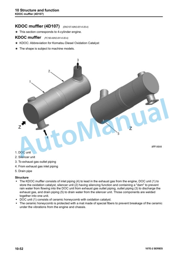
- 4.3.20. KDOC muffler (4D107)
- 4.3.21. KDPF (6D107)
- 4.4. Engine main body parts
- 4.4.1. Cylinder head
- 4.4.2. Cylinder block
- 4.4.3. Main moving parts
- 4.4.4. Vibration damper (6D107)
- 4.4.5. Timing gear
- 4.4.6. Front cover
- 4.4.7. Valve system
- 4.4.8. Flywheel
- 4.5. Lubrication system
- 4.5.1. Lubrication system parts layout drawing (4D107)
- 4.5.2. Lubrication system parts layout drawing (6D107)
- 4.5.3. Lubrication system circuit diagram (4D107)
- 4.5.4. Lubrication system circuit diagram (6D107)
- 4.5.5. Oil pump
- 4.5.6. Boost oil pump (6D107)
- 4.5.7. Oil filter
- 4.5.8. Oil cooler
- 4.5.9. Regulator valve
- 4.5.10. Safety valve
- 4.5.11. Oil pan
- 4.6. Fuel system
- 4.6.1. Fuel system parts layout drawing
- 4.6.2. Fuel system circuit diagram
- 4.6.3. Supply pump
- 4.6.4. Fuel cooler
- 4.6.5. Prefilter
- 4.6.6. Main filter
- 4.7. Cooling system
- 4.7.1. Cooling system parts layout drawing
- 4.7.2. Cooling system circuit diagram (4D107)
- 4.7.3. Cooling system circuit diagram (6D107)
- 4.7.4. Drive pulley
- 4.7.5. Water pump
- 4.7.6. Thermostat
- 4.8. Electrical equipment
- 4.8.1. Alternator
- 4.8.2. Starting motor
- 4.8.3. Intake air heater
- 4.8.4. Engine wiring harness (4D107)
- 4.8.5. Engine wiring harness (6D107)
- 4.8.6. Engine controller (4D107)
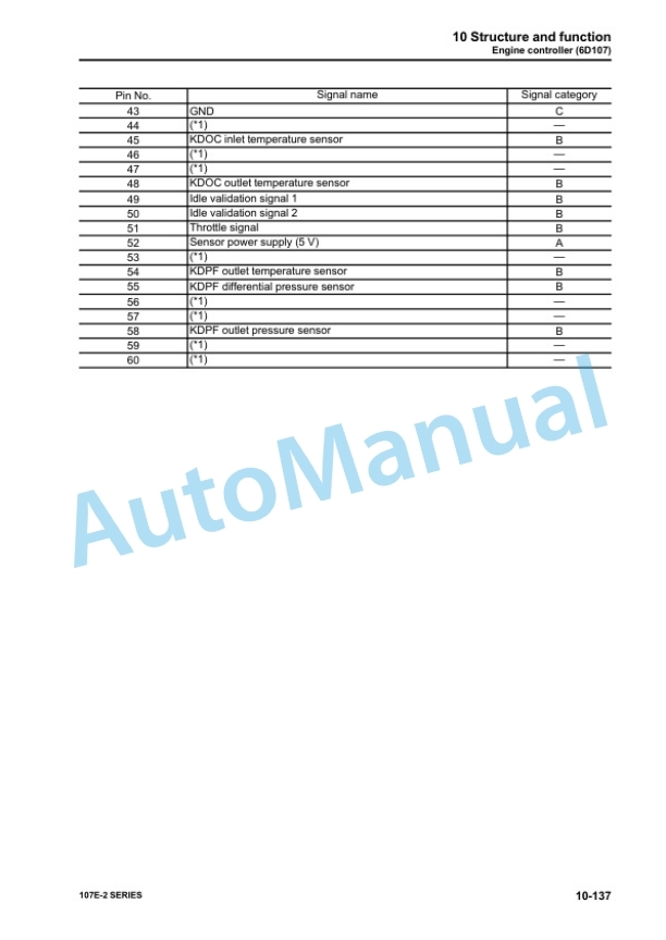
- 4.8.7. Engine controller (6D107)
- 4.8.8. Sensor
- 5. Standard value tables
- 5.1. Table of contents
- 5.2. Standard service value table
- 5.2.1. Standard value table for engine
- 5.2.2. Runningin standard and performance test standard
- 6. Disassembly and assembly
- 6.1. Table of contents
- 6.2. Related information on disassembly and assembly
- 6.2.1. How to read this manual
- 6.2.2. Coating materials list
- 6.2.3. Special tool list
- 6.2.4. Sketch of special tool
- 6.3. Disassembly and assembly
- 6.3.1. General disassembly of engine
- 6.3.2. General assembly of engine
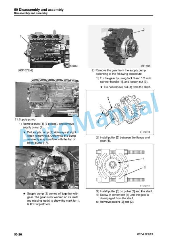
- 6.3.3. Removal and installation procedure of supply pump unit alone
- 6.3.4. Engine front oil seal replacement procedure
- 6.3.5. Engine rear oil seal replacement procedure
- 7. Maintenance standard
- 7.1. Table of contents
- 7.2. Intake and exhaust system parts
- 7.2.1. VFT (4D107)
- 7.2.2. VGT(6D107)
- 7.3. Engine main body parts
- 7.3.1. Cylinder head
- 7.3.2. Cylinder block
- 7.3.3. Crankshaft
- 7.3.4. Piston
- 7.3.5. Connecting rod
- 7.3.6. Vibration damper (6D107)
- 7.3.7. Timing gear
- 7.3.8. Camshaft
- 7.3.9. Valve and valve guide
- 7.3.10. Rocker arm
- 7.3.11. Tappet
- 7.3.12. Flywheel
- 7.4. Lubrication system
- 7.4.1. Oil pump
- 8. INDEX



There are no reviews yet.