

Description
-
Model List:
- PC4000-6 Diesel Hydraulic Excavator
- 1. COVER
- 2. Foreword
- 2.1. Introduction
- 2.2. Safety Instructions
- 3. Specification
- 3.1. Specification PC4000
- 4. Structure, Function
- 4.1. Table of Contents
- 4.2. INTRODUCTION
- 4.2.1. I Contents of the Binder
- 4.2.2. II Foreword
- 4.2.3. III Explanation of Abbrevations
- 4.2.4. IV EXPLANATION OF ABBREVATIONS
- 4.2.5. V DIAGRAMS AND ILLUSTRATIONS IN THIS MANUAL
- 4.3. III. SPECIFICATIONS
- 4.3.1. III.I Lifting Gears
- 4.3.2. III.II Standard Tightening Torque Chart
- 4.3.3. III.III Conversion Table
- 4.3.4. III.IV General Specifications
- 4.3.5. III.V BLIND PLUGS
- 4.3.6. III.VI CLASSIFICATION OF THREADS TO THE NOMINAL WIDTH
- 4.3.7. III.VII PLUGS AND FITTINGS ACCORDING TO ISO 84341 / DIN 2353
- 4.4. MAIN ASSEMBLY GROUPS
- 4.4.1. General Layout
- 4.4.2. Superstructure
- 4.4.3. Machine House
- 4.4.4. Hydraulic Oil Reservoir
- 4.4.5. Hydraulic Oil Cooler
- 4.4.6. Fuel Tank
- 4.4.7. Counterweight
- 4.4.8. Cab Support
- 4.4.9. Operators Cab
- 4.4.10. Control Blocks
- 4.4.11. Swing Gears
- 4.4.12. Undercarriage
- 4.4.13. Backhoe Attachment (BHA)
- 4.4.14. Front Shovel Attachment (FSA)
- 4.5. DRIVE
- 4.5.1. Prime Drive Assembly
- 4.5.2. Engine and PTO Mounts
- 4.5.3. Fan Drive and Radiator Assembly
- 4.5.4. FAN DRIVE AND RADIATOR ASSEMBLY
- 4.5.5. PUMP DISTRIBUTOR GEARBOX (PTO)
- 4.5.6. Air Filter
- 4.6. HYDRAULIC OIL TANK
- 4.6.1. General Layout
- 4.6.2. Main Oil Tank, Location of Electric Equipment.
- 4.6.3. Suction Oil Reservoir with Strainers
- 4.6.4. Return Oil Collector Tube with Strainer
- 4.6.5. Back Pressure Valve
- 4.6.6. Transfer Pump
- 4.6.7. Return and Leak Oil Filter
- 4.6.8. Breather Filter
- 4.7. HYDRAULIC OIL COOLING
- 4.7.1. OVERALL VIEW OF THE HYDRAULIC OIL COOLING
- 4.7.2. Function of the Hydraulic Oil Cooling Circuit
- 4.7.3. Adjustment of the Back Pressure Valve
- 4.7.4. Fan Drive (Two Stage Cooler Fan RPM Control)
- 4.7.5. Adjustment of the Cooler Fan Drive Speed
- 4.8. CONTROLLING
- 4.8.1. General Layout
- 4.8.2. Control and Filter Panel Location of Components
- 4.8.3. Pilot Pressure Supply and Adjustments
- 4.8.4. Function Electro Hydraulic Control SYSTEM
- 4.8.5. Potentiometer Control (Lever, Joy Stick)
- 4.8.6. Potentiometer Control (Pedal)
- 4.8.7. Proportional Amplifier Module, Type A
- 4.8.8. Proportional Amplifier Module, Type B
- 4.8.9. Ramp Time Module
- 4.8.10. Adjustments of Amplifier Modules
- 4.8.11. Adjusting the Ramp Time Module
- 4.9. COMPONENTS
- 4.9.1. Main Control Blocks and High Pressure Filter (FSA)
- 4.9.2. Main Control Blocks and High Pressure Filter (BHA)
- 4.9.3. Distributor Manifold Location of Restrictor Blocks and Anti Cavitation Valves (FSA)
- 4.9.4. Distributor Manifold Location of Restrictor Blocks and Anti Cavitation Valves (BHA)
- 4.9.5. Single Control Blocks (Floating) for Stick and Boom (FSA)
- 4.9.6. Restrictor Block with Pressure Relief Valve
- 4.9.7. Anti cavitation valve block
- 4.9.8. Remote Control Valves
- 4.9.9. Directional Solenoid Valves (Three Positions / 4Ways)
- 4.9.10. Proportional Solenoid Valve
- 4.9.11. High Pressure Filter
- 4.9.12. Control Blocks and Valves
- 4.9.13. Travel Brake Valve
- 4.9.14. Pressure Reducing Valve
- 4.9.15. Directional Solenoid Valves (Two Positions / 4Ways)
- 4.9.16. Pressure Increasing Valve
- 4.9.17. Hydraulic Cylinder
- 4.9.18. Swing Ring
- 4.10. MAIN HYDRAULIC PUMPS AND PUMP REGULATION
- 4.10.1. General
- 4.10.2. Main Pumps
- 4.10.3. Electronic Pump Regulation System
- 4.10.4. Hydraulic Constant Regulation System
- 4.10.5. Determination of the Peak Point (Engine Performance)
- 4.10.6. Engine Speed Sensor (Pick up)
- 4.10.7. Energy Efficiency
- 4.11. OPERATING HYDRAULICS
- 4.11.1. General
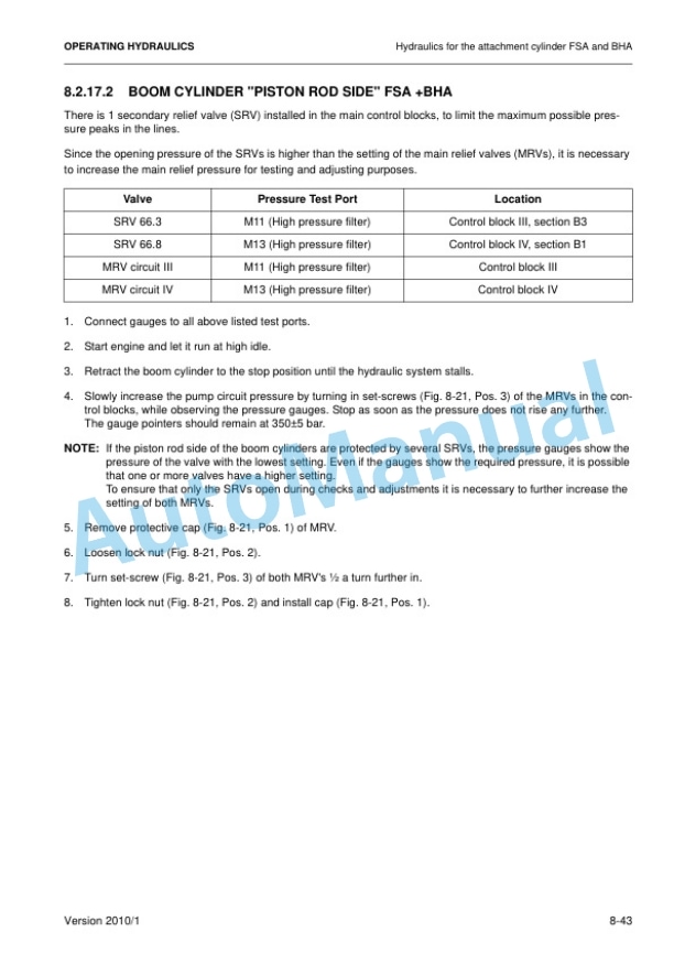
- 4.11.2. Hydraulic for the Attachment Cylinder FSA and BHA
- 4.11.3. Hydraulic for the Swing Circuit
- 4.11.4. Hydraulic for the Travel Circuit
- 4.12. HYDRAULIC TRACK TENSIONING SYSTEM
- 4.12.1. General
- 4.12.2. FUNCTIONAL DESCRIPTION
- 4.12.3. PRESSURE DOUBLE STAGE VALVE
- 4.12.4. TENSIONING CYLINDER
- 4.12.5. ADJUSTMENTS / CHECKS
- 4.13. ACCESS LADDER HYDRAULICALLY OPERATED
- 4.13.1. General
- 4.13.2. FUNCTION OF HYDRAULICALLY OPERATED ACCESS LADDER
- 4.13.3. Adjustments / Checks
- 4.14. CENTRAL REFILLING SYSTEM (SERVICE ARM)
- 4.14.1. General
- 4.14.2. Function
- 4.15. HINTS FOR READING THE HYDRAULIC DIAGRAM
- 4.15.1. General
- 4.15.2. HYDRAULIC SYMBOLS
- 4.16. HINTS FOR READING THE ELECTRIC CIRCUIT DIAGRAM
- 4.16.1. GENERAL
- 4.16.2. REFERENCE DESIGNATION OF THE ELECTRICAL COMPONENTS
- 4.16.3. GRAPHICAL SYMBOLS
- 4.16.4. Drawing Concept
- 4.16.5. CABLE MARKING
- 4.16.6. TABLE OF NEW AND OLD COMPONENT DESIGNATIONS
- 4.17. VEHICLE HEALTH MONITORING SYSTEM MTC CONTROL SYSTEM
- 4.17.1. General
- 4.17.2. Specifications for Operators
- 4.17.3. FLOW CHARTS (14) VHMS MAIN SCREENS
- 4.17.4. VHMS SERVICE LEVEL
- 4.17.5. INTERFACECONNECTION VHMSCONTROLLER
- 4.17.6. WIRING OF THE VHMSCONTROLLER
- 4.17.7. GLOBAL LAYOUT OF THE MTC CONTROL SYSTEM
- 4.17.8. GLOBAL LAYOUT OF THE INTERNAL CAN BUS
- 4.17.9. THE NODES IN THE CAN BUS SYSTEM
- 4.18. AUTOMATIC LUBRICATION SYSTEMS
- 4.18.1. GENERAL OVERVIEW CLS SLS
- 4.18.2. BASIC FUNCTION OF THE LUBRICATION SYSTEMS
- 4.18.3. CENTRAL LUBRICATION SYSTEM (CLS)
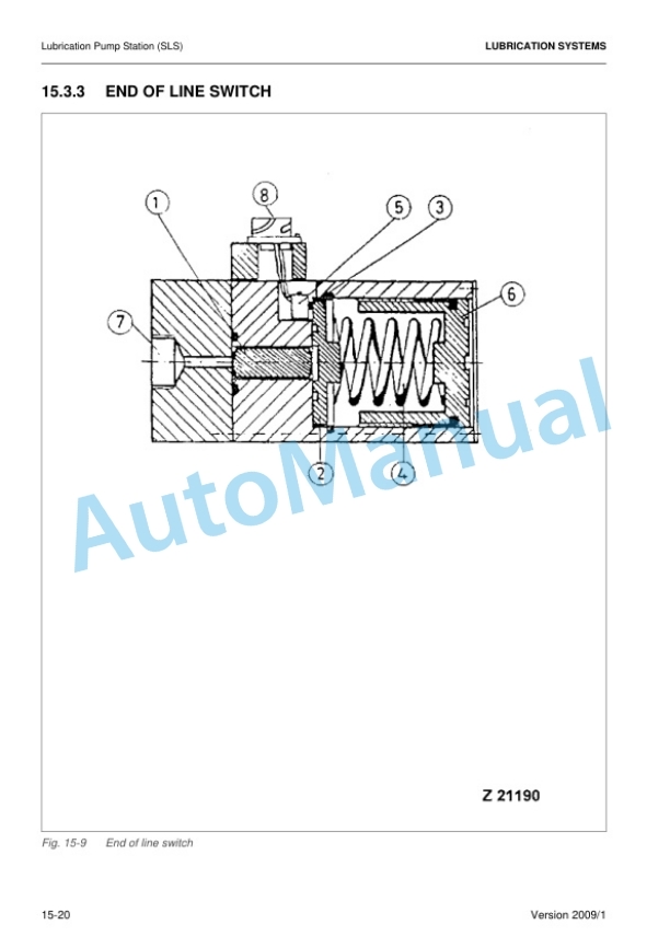
- 4.18.4. LUBRICATION PUMP STATION (SLS)
- 4.18.5. Adjustments
- 4.18.6. Troubleshooting
- 4.18.7. Commissioning
- 4.19. Troubleshooting
- 4.19.1. Table of Contents
- 4.19.2. SAFETY
- 4.19.3. Introduction general information for troubleshooting
- 4.19.4. Mounting locations, connector types and electrical standard values
- 4.19.5. Troubleshooting by trouble code
- 4.19.6. Troubleshooting by symptoms
- 5. Disassembly and Assembly
- 5.1. Introduction
- 5.1.1. Contents of the binder
- 5.1.2. Foreword
- 5.2. Safety
- 5.2.1. Safety Instructions
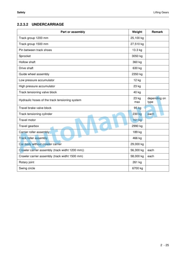
- 5.2.2. Lifting Gears
- 5.2.3. Torque charts according to DIN
- 5.2.4. Conversation table
- 5.2.5. Explanation of abbreviations
- 5.3. Superstructure
- 5.3.1. Diesel Engine
- 5.3.3. Hydraulics
- 5.3.4. Slew Drive
- 5.3.5. Lubrication pumps
- 5.3.6. Pump controller MC7
- 5.3.7. Operators Cab
- 5.3.8. Counterweight
- 5.3.9. Superstructure Lifting
- 5.3.10. Fuel Tank
- 5.4. Undercarriage
- 5.4.1. Travel System
- 5.4.2. Car body
- 5.5. Attachment
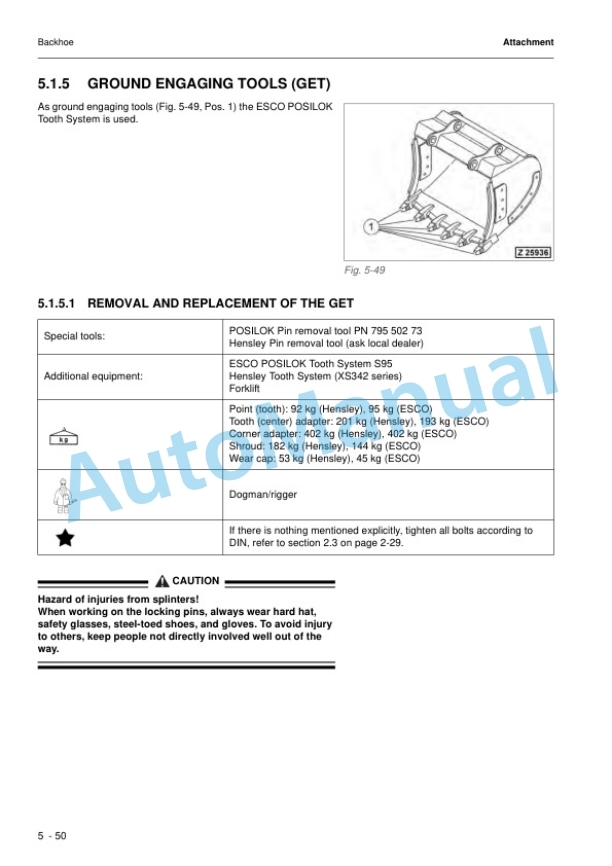
- 5.5.1. Backhoe
- 5.5.2. Faceshovel
- 5.5.3. Metering valves (grease injectors) at the attachment
- 5.5.4. Cylinder bypass test
- 5.6. Appendix
- 5.6.1. Fuel and Lubricants
- 5.6.2. Filling Capacities
- 5.6.3. Tools List
- 5.6.4. Work instructions
- 5.6.5. Service Bulletins










Reviews
There are no reviews yet.