
Description
-
Model List:
- PC900LC-11 Hydraulic Excavator
- 1. Cover
- 2. FOREWORD
- 3. CONTENTS
- 4. SAFETY INFORMATION
- 4.1. SAFETY NOTICE FOR OPERATION
- 4.2. PRECAUTIONS TO PREVENT FIRE
- 4.3. ACTIONS IF FIRE OCCURS
- 4.4. PRECAUTIONS FOR DISPOSING OF WASTE MATERIALS
- 4.5. ACTIONS TAKEN TO MEET EXHAUST GAS REGULATIONS
- 4.6. PRECAUTIONS FOR DEF
- 4.7. STORE AdBlue/DEF
- 4.8. PRECAUTIONS FOR HANDLING HYDRAULIC EQUIPMENT
- 4.9. PRECAUTIONS FOR DISCONNECTION AND CONNECTION OF PIPINGS
- 4.10. PRECAUTIONS FOR HANDLING ELECTRICAL EQUIPMENT
- 4.11. PRECAUTIONS FOR HANDLING FUEL SYSTEM EQUIPMENT
- 5. HANDLING OF TIEOFF ANCHOR POINTS
- 6. BE CAREFUL NOT TO HIT BUCKET WHEN RETRACTING WORK EQUIPMENT
- 7. SPECIFICATIONS
- 8. PRECAUTIONS FOR FIELD ASSEMBLY
- 9. DISPOSAL OF REMOVED PARTS
- 10. ASSEMBLY PROCEDURE, FACILITY USED, AND SCHEDULE
- 11. KIT LAYOUT DIAGRAM
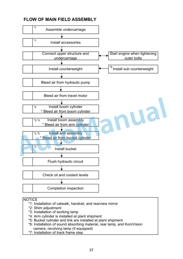
- 12. FLOW OF MAIN FIELD ASSEMBLY
- 13. TRANSPORTATION PACKING STYLE
- 14. FIELD ASSEMBLY TOOLS LIST
- 15. TIGHTENING TORQUE
- 16. COATING MATERIALS
- 17. SELECTION OF WIRE ROPES USED FOR ASSEMBLY
- 18. SELECTION OF NYLON SLINGS USED FOR ASSEMBLY
- 19. ASSEMBLY OF CHASSIS
- 19.1. A1 Replacement of return filter (Standard > Flushing)
- 19.2. A2 Installation of R.H. and L.H. track frames
- 19.3. A3 Installation of travel piping
- 19.4. A4 Installation of step
- 19.5. A5 Sticking revolving frame sheets
- 19.6. A6 Installation of L.H. side step
- 19.7. A7 Installation of R.H. side step
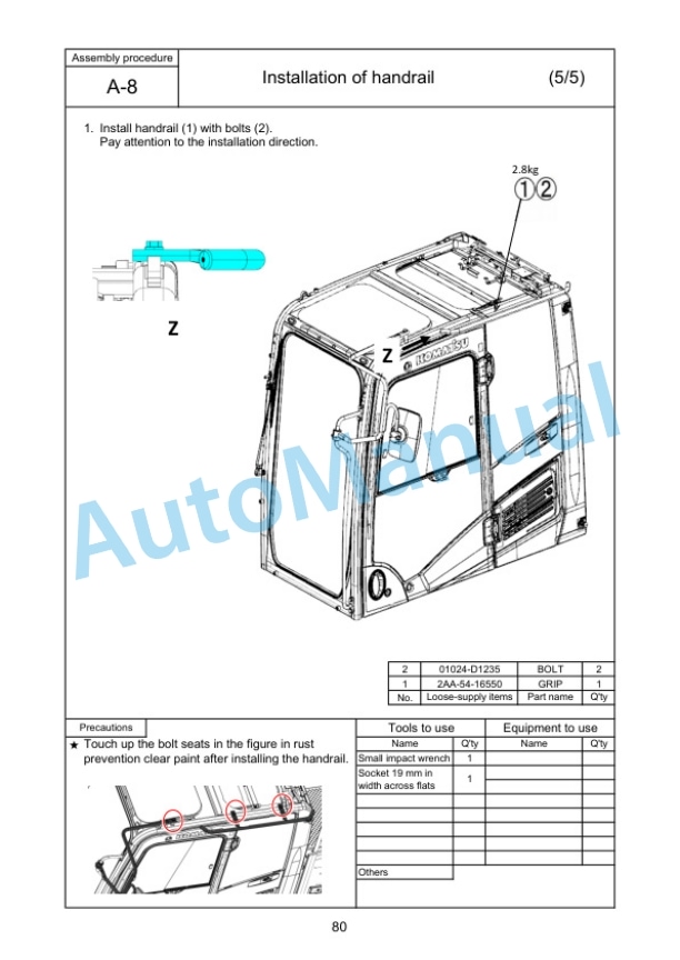
- 19.8. A8 Installation of handrail
- 19.9. A9 Installation of R.H. rearview mirror
- 19.10. A10 Installation of L.H. rearview mirror
- 19.11. A11 Installation of R.H. side step
- 19.12. A12 Installation of swivel travel piping
- 19.13. A13 Sticking counterweight sheets
- 19.14. A14 Assembly procedure of KomVision camera
- 19.15. A15 Installation of counterweight revolving lamp (if equipped)
- 19.16. A16 Installation of counterweight rear lamp
- 19.17. A17 Installation of counterweight
- 19.18. A18 Installation of cab top step lamp
- 19.19. A19 Installation of cab revolving lamp (if equipped)
- 19.20. A20 Bleed air from hydraulic pump
- 19.21. A21 Bleed air from travel motor
- 19.22. A22 Installation of travel piping covers
- 19.23. A23 Installation of track frame undercovers
- 19.24. A24 Installation of travel motor guards
- 19.25. A25 Adjustment of track tension
- 19.26. A26 Installation of fire extinguisher (if equipped)
- 19.27. A27 Installation of transportation jigs (muffler)
- 20. Assembly of work equipment
- 20.1. B1 Release pressure remaining in hydraulic circuit
- 20.2. B2 Installation of boom cylinder to revolving frame
- 20.3. B3 Installation of boom cylinder hoses
- 20.4. B4 Bleed air from cylinder
- 20.5. B5 Installation of dust seal to boom foot
- 20.6. B6 Installation of boom assembly
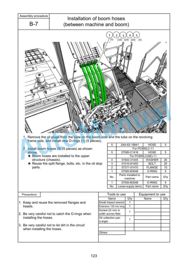
- 20.7. B7 Installation of boom hoses (between machine and boom)
- 20.8. B8 Installation of boom cylinder
- 20.9. B9 Installation of arm assembly
- 20.10. B10 Installation of hoses between boom and bucket cylinder
- 20.11. B11 Installation of bucket assembly
- 20.12. B12 Clearance standard for installation of work equipment
- 20.13. B13 Installation of work equipment grease piping
- 20.14. B14 Installation of work equipment lamp wiring
- 20.15. B15 Greasing after assembling work equipment
- 21. . Installation of counterweight remover (Optional)
- 21.1. D1 Sticking counterweight sheets (Machine with optional remover)
- 21.2. D2 Sticking revolving frame sheets
- 21.3. D3 Installation of counterweight remover
- 21.4. D4 Greasing
- 21.5. D5 Installation of counterweight
- 21.6. D6 Assembly procedure of KomVision camera
- 22. Testing and maintenance procedures after completing assembly
- 22.1. M1 Check hydraulic tank oil level and add oil
- 22.2. M2 Flushing of hydraulic circuit
- 22.3. M3 Replacement of return filter (Flushing > Standard)
- 22.4. M4 Check of oil and coolant levels at each section
- 22.5. M5 Places to touch up after field assembly
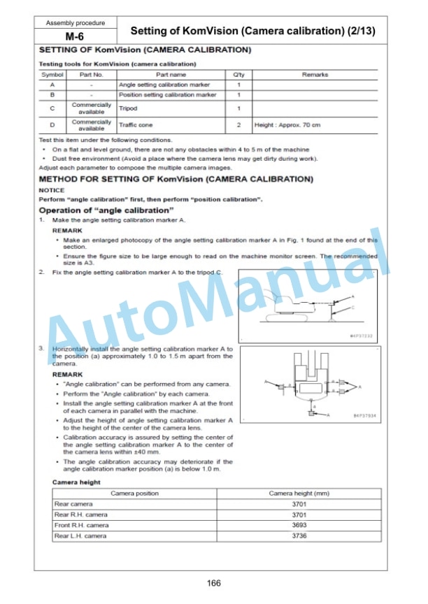
- 22.6. M6 Setting of KomVision (Camera calibration)
- 22.7. M7 Inspection method of 12 m visibility (KomVision)
- 22.8. M8 Check display of failure code
- 22.9. M9 Installation of fuel tank oil filler lock
- 23. Field assembly inspection check sheet





Reviews
There are no reviews yet.