
Description
-
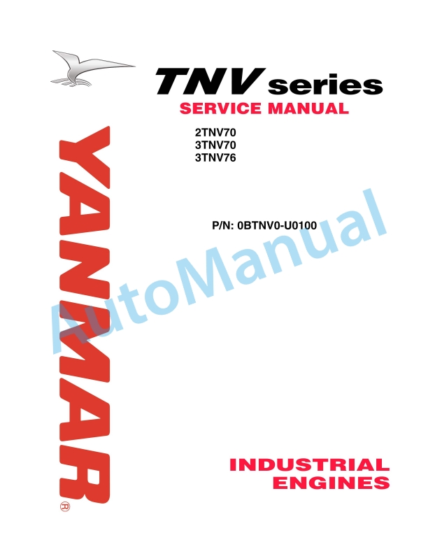
Model List:
- 2TNV70, 3TNV70, 3TNV76 Industrial Engines
- 1. PREFACE
- 2. SAFETY LABELS
- 3. Safety Precautions
- 4. Precautions for Service Work
- 5. CONTENTS
- 6. General
- 6.1. Engine Nomenclature
- 6.2. Specifications
- 6.3. Fuel Oil, Lubricating Oil and Cooling water
- 6.3.1. Fuel oil
- 6.3.2. Lubricating oil
- 6.3.3. Cooling water
- 6.4. Engine External Views
- 6.5. Structural Description
- 6.6. Exhaust gas emission regulation
- 6.6.1. The Emission Standard in USA
- 6.6.2. Engine identification
- 6.6.3. Guarantee Conditions for the EPA Emission Standard
- 7. Inspection and Adjustment
- 7.1. Periodic Maintenance Schedule
- 7.2. Periodic Inspection and Maintenance Procedure
- 7.2.1. Check before Daily Operation
- 7.2.2. inspection after initial 50 hours operation
- 7.2.3. Inspection every 50 hours
- 7.2.4. Inspection every 250 hours or 3 months
- 7.2.5. Inspection every 500 hours or 6 months
- 7.2.6. Inspection every 1,000 hours or one year
- 7.2.7. Inspection every 2000 hours or 2 years
- 7.3. Adjusting the no-load maximum or minimum speed
- 7.4. Sensor Inspection
- 7.4.1. Oil pressure switch
- 7.4.2. Thermo switch
- 7.5. Water leak check in cooling water system
- 7.6. Radiator cap inspection
- 7.7. Thermostat inspection
- 7.8. Adjusting Operation
- 7.9. Long storage
- 8. TROUBLESHOOTING
- 8.1. Preparation before troubleshooting
- 8.2. Quick Reference Table for Troubleshooting
- 8.3. Troubleshooting by measuring Compression Pressure
- 9. Disassembly, Inspection and Reassembly of Engines
- 9.1. Complete disassembly and reassembly
- 9.1.1. Introduction
- 9.1.2. Special service tools
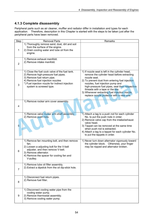
- 9.1.3. Complete disassembly
- 9.1.4. Precautions before and during reassembly
- 9.1.5. Adjusting operation
- 9.2. Cylinder Head Disassembly, Inspection and Reassembly
- 9.2.1. Components (2-valve cylinder head)
- 9.2.2. Disassembly procedure
- 9.2.3. Reassembly procedure
- 9.2.4. Servicing points
- 9.2.5. Parts Inspection and measurement
- 9.2.6. Valve seat correction
- 9.2.7. Valve guide replacement
- 9.2.8. Valve stem seal replacement
- 9.3. Gear Train and Camshaft
- 9.3.1. Components
- 9.3.2. Disassembly procedure
- 9.3.3. Reassembly procedure
- 9.3.4. Servicing points
- 9.3.5. Parts inspection and measurement
- 9.3.6. Oil seal replacement
- 9.3.7. Camshaft bushing replacement
- 9.4. Cylinder Block
- 9.4.1. Components
- 9.4.2. Disassembly procedure
- 9.4.3. Reassembly procedure
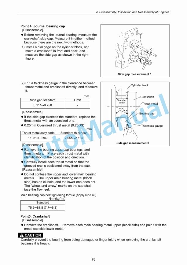
- 9.4.4. Servicing points
- 9.4.5. Parts inspection and measurement
- 9.4.6. Cylinder bore correction
- 9.4.7. Piston pin metal replacement
- 9.4.8. Oil seal replacement (Flywheel housing side)
- 10. LUBRICATION SYSTEM
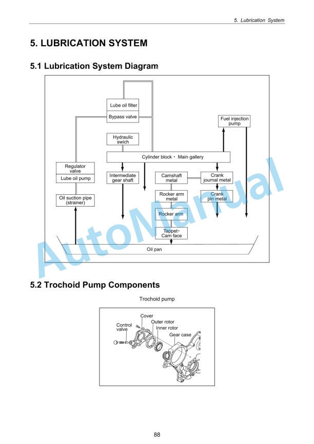
- 10.1. Lubrication System Diagram
- 10.2. Trochoid Pump Components
- 10.3. Disassembly(Reverse the below procedure for reassembly)
- 10.4. Servicing Points
- 10.5. Parts Inspection and Measurement
- 10.5.1. Trochoid pump inspection and measurement
- 11. COOLING SYSTEM
- 11.1. Cooling water System
- 11.2. Cooling Water Pump Components91
- 11.3. Disassembly (Reverse the below procedure for reassembly)
- 11.4. Servicing Points
- 12. FUEL INJECTION PUMP / GOVERNOR
- 12.1. Introduction
- 12.2. Fuel Injection Pump
- 12.2.1. Fuel system diagram
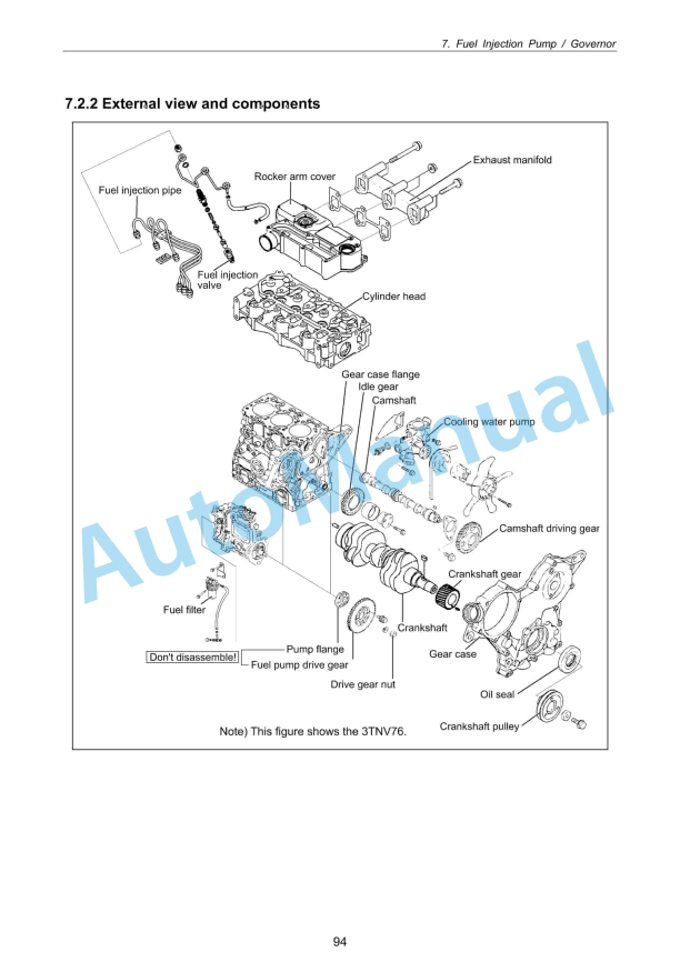
- 12.2.2. External view and components
- 12.2.3. Disassembly procedure
- 12.2.4. Reassembly procedure
- 12.2.5. Confirmation and adjustment of fuel injection timing
- 12.2.6. Confirmation and adjustment of no-load maximum and minimum speed
- 13. The specifications of a starting motorand the characteristics
- 13.1. The specifications and the characteristics
- 13.1.1. Specifications
- 13.1.2. Characteristics
- 13.2. The structure of a starting motor and the wiring diagram
- 13.2.1. Structure
- 13.2.2. Wiring diagram of a starting motor
- 13.3. Performance
- 14. ALTERNATOR
- 14.1. Alternator
- 14.1.1. Specifications
- 14.1.2. Structure
- 14.1.3. Wiring diagram
- 14.1.4. Standard output characteristics
- 14.1.5. Inspection
- 14.2. Alternator
- 14.2.1. Components
- 14.2.2. Specifications
- 14.2.3. Wiring diagram
- 14.2.4. Standard output characteristics
- 14.2.5. Inspection
- 14.3. Troubleshooting
- 15. Electric Wiring
- 15.1. Electric Wiring Diagram
- 15.1.1. Alternator
- 15.1.2. Starting motor
- 15.1.3. Current limiter
- 15.1.4. Section area and resistance of electric wire
- 16. SERVICE STANDARDS
- 16.1. Engine Tuning
- 16.2. Engine Body
- 16.2.1. Cylinder head
- 16.2.2. Gear train and camshaft
- 16.2.3. Cylinder block
- 16.3. Lubricating Oil System (Trochoid Pump)
- 17. Tightening Torque for Bolts and Nuts
- 17.1. Tightening Torques for Main Bolts and Nuts
- 17.2. Tightening Torques for Standard Bolts and Nuts
- 18. BACKCOVER


,%202GM20(F)(C),%203GM30(F)(C),%203HM35(F)(C)%20Engine%20Service%20Manual&url=https://pdfrepairmanual.com/docs/yanmar-1gm10c-2gm20fc-3gm30fc-3hm35fc-engine-service-manual/&media=https://pdfrepairmanual.com/wp-content/uploads/2026/01/yanmar-1gm10c-2gm20fc-3gm30fc-3hm35fc-engine-service-manual-1.jpg)


,%202GM(F)(L),%203GM(D)(F)(L),%203HM(F)(L)%20Engine%20Service%20Manual&url=https://pdfrepairmanual.com/docs/yanmar-1gm10l-2gmfl-3gmdfl-3hmfl-engine-service-manual/&media=https://pdfrepairmanual.com/wp-content/uploads/2026/01/yanmar-1gm10l-2gmfl-3gmdfl-3hmfl-engine-service-manual-1.jpg)
(C)(M)E%20Service%20Manual&url=https://pdfrepairmanual.com/docs/yanmar-3jh4bcme-service-manual/&media=https://pdfrepairmanual.com/wp-content/uploads/2026/01/yanmar-3jh4bcme-service-manual-1.jpg)
,%202GM(F)(L),%203GM(D)(F)(L),%203HM(F)(L)%20Marine%20Diesel%20Engine%20Service%20Manual&url=https://pdfrepairmanual.com/docs/yanmar-1gm10l-2gmfl-3gmdfl-3hmfl-marine-diesel-engine-service-manual/&media=https://pdfrepairmanual.com/wp-content/uploads/2026/01/yanmar-1gm10l-2gmfl-3gmdfl-3hmfl-marine-diesel-engine-service-manual-1.jpg)

There are no reviews yet.