
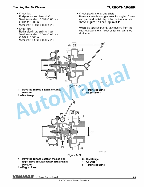
Description
-
Model List:
- 3JH5E, 4JH5E, 4JH4-TE, 4JH4-HTE Marine Engine
- 1. Table of Contents
- 2. Introduction
- 2.1. Revision History
- 2.1.1. Revision Control Table
- 2.2. Safety Statements
- 2.3. Safety Precautions
- 2.4. Location of Safety Labels
- 3. General Service Information
- 3.1. Safety Precautions
- 3.2. Engine Outline Drawings
- 3.2.1. H5E Models
- 3.2.2. H5E Models
- 3.2.3. H4-TE Models
- 3.2.4. H4-HTE Models
- 3.3. Piping Diagrams
- 3.3.1. H5E Models
- 3.3.2. H5E Models
- 3.3.3. H4-TE Models
- 3.3.4. H4-HTE Models
- 3.4. Exhaust Gas Emission Regulations
- 3.4.1. Engine Identification (EPA / CARB)
- 3.4.2. Emission Control Label (EPA / CARB)
- 3.5. Location of Nameplates
- 3.5.1. Engine Nameplates (Typical)
- 3.6. Diesel Fuel
- 3.6.1. Diesel Fuel Specifications
- 3.6.2. Bleeding the Fuel System
- 3.7. Engine Oil
- 3.7.1. Engine Oil Specifications
- 3.8. Engine Coolant
- 3.8.1. Engine Coolant Specifications
- 3.9. Principal Engine Specifications
- 3.9.1. H5E Engine Specifications
- 3.9.2. H4-HTE Engine Specifications
- 3.10. Tightening Torques
- 3.10.1. Hexagon Bolts and Nuts
- 3.10.2. Hose Clamps
- 3.11. Prepare Engine for Long-Term Storage
- 3.12. Abbreviations and Symbols
- 3.12.1. Symbols
- 3.13. Unit Conversions
- 3.13.1. Unit Prefixes
- 3.13.2. Units of Length
- 3.13.3. Units of Volume
- 3.13.4. Units of Mass
- 3.13.5. Units of Force
- 3.13.6. Units of Torque
- 3.13.7. Units of Pressure
- 3.13.8. Units of Power
- 3.13.9. Units of Temperature
- 4. Periodic Maintenance
- 4.1. Safety Precautions
- 4.2. Introduction
- 4.2.1. The Importance of Periodic Maintenance
- 4.2.2. Performing Periodic Maintenance
- 4.2.3. Yanmar Replacement Parts
- 4.2.4. Required EPA Maintenance
- 4.3. EPA Requirements
- 4.3.1. Conditions to Ensure Compliance with EPA Emission Standards
- 4.3.2. Inspection and Maintenance
- 4.4. Periodic Maintenance Schedule
- 4.4.1. Inspection and Maintenance of EPA Emission-Related Parts
- 4.4.2. Inspection and Maintenance of EPA Emission-Related Parts for Non-Road and CI Marine Engines
- 4.5. Periodic Maintenance Procedures
- 4.5.1. After Initial 50 Hours of Operation
- 4.5.2. Every 50 Hours of Operation
- 4.5.3. Every 250 Hours of Operation
- 4.5.4. Every 500 Hours of Operation
- 4.5.5. Every 1000 Hours of Operation
- 4.6. Safety Precautions
- 4.7. Introduction
- 4.8. Specifications
- 4.8.1. General Information
- 4.8.2. Test and Adjustment Specifications
- 4.8.3. Repair Specifications
- 4.9. Special Torque Chart
- 4.10. Standard Torque Chart (w/o Lubricating Oil)
- 4.11. Special Service Tools
- 4.12. Measuring Instruments
- 4.13. Sealants and Compounds
- 4.14. Tests and Adjustments
- 4.14.1. Test Compression
- 4.15. Disassembly
- 4.16. Inspection
- 4.16.1. Cylinder Block
- 4.16.2. Cylinder Head
- 4.16.3. Piston and Piston Rings
- 4.16.4. Connecting Rod
- 4.16.5. Crankshaft and Main Bearings
- 4.16.6. Camshaft and Tappets
- 4.16.7. Timing Gear
- 4.16.8. Flywheel and Housing
- 4.17. Assembly
- 4.17.1. Checking and Adjusting Remote Control Operation
- 5. Fuel System
- 5.1. Safety Precautions
- 5.2. Introduction
- 5.3. Specifications
- 5.3.1. Test and Adjustment Specifications
- 5.3.2. Special Torque Chart
- 5.4. Special Service Tools
- 5.5. Fuel System Components
- 5.5.1. H4E-HT / 4JH4-HTE Engines
- 5.6. Fuel System Diagram
- 5.7. Fuel System Tests
- 5.7.1. Measuring Fuel Feed Pump Pressure
- 5.7.2. Testing Return Fuel Pressure
- 5.8. Servicing the Fuel System
- 5.8.1. Removing the Fuel Injection Nozzle
- 5.8.2. Cleaning Fuel Injection Nozzle Cavities
- 5.8.3. Installing Fuel Injection Nozzles
- 5.8.4. Removing Fuel Injection Lines
- 5.8.5. Installing Fuel Injection Lines
- 5.8.6. Replacing the Fuel Injection Pump
- 5.8.7. Adjusting Fuel Injection Timing
- 5.9. MP2 Fuel Injection Pump System (3 / 4JH5E)
- 5.9.1. Introduction
- 5.9.2. Fuel Injection Pump
- 5.9.3. Stop Solenoid
- 5.9.4. Trochoid Fuel Pump
- 5.10. Fuel System Specifications
- 5.10.1. Special Torque Chart
- 5.10.2. Test and Adjustment Specifications
- 5.11. Special Service Tools
- 5.12. Measuring Instruments
- 5.13. Fuel System Components
- 5.14. Fuel Injection Pump
- 5.14.1. Removing the Fuel Injection Pump
- 5.14.2. Installing the Fuel Injection Pump
- 5.15. Checking and Adjusting Fuel Injection Timing
- 5.15.1. Determining the Fuel Injection Timing Specification
- 5.15.2. Checking Fuel Injection Timing
- 5.15.3. Adjusting Fuel Injection Timing
- 5.15.4. Fuel Injection Pump Service Data
- 5.15.5. Fuel Line Replacement Filter
- 5.15.6. Replacing the Injection Nozzle Return
- 5.15.7. Bleeding the Fuel System
- 5.16. Fuel Injectors
- 5.16.1. Removing Fuel Injectors
- 5.16.2. Testing Fuel Injectors
- 5.16.3. Disassembling and Inspecting Fuel Injectors
- 5.16.4. Adjusting Fuel Injector Pressure
- 5.16.5. Reassembling the Fuel Injectors
- 6. Cooling System
- 6.1. Safety Precautions
- 6.2. Introduction
- 6.3. Specifications
- 6.3.1. Test and Adjustment Specifications
- 6.3.2. Repair Specifications
- 6.4. Special Service Tools
- 6.5. Measuring Instruments
- 6.6. Cooling Flow Diagram
- 6.7. Tests and Adjustments
- 6.7.1. Pressure Testing Cooling System and Filler Cap
- 6.7.2. Testing Thermostat
- 6.8. Draining / Refilling Seawater Cooling System
- 6.8.1. Draining and Filling Closed Cooling System
- 6.9. Removing / Installing Intercooler (4JH4-HTE)
- 6.10. Disassembling and Assembling Intercooler
- 6.11. Removing and Installing Heat Exchanger
- 6.12. Disassembling / Assembling Heat Exchanger
- 6.13. Removing and Installing Coolant Pump
- 6.14. Removing and Installing Thermostat
- 6.14.1. Removal
- 6.14.2. Installation
- 6.15. Seawater Pump
- 6.15.1. Inspecting / Replacing Impeller
- 6.15.2. Removing and Installing Seawater Pump and Pump Drive Gear
- 6.15.3. Replacing Coolant Pump Belt and Pulley
- 6.16. Coolant Recovery Tank
- 6.16.1. Coolant Recovery Tank Function
- 6.16.2. Mounting the Coolant Recovery Tank
- 6.16.3. Before Using Coolant Recovery Tank
- 6.17. Bilge Pump and Bilge Strainer (Optional)
- 6.17.1. Description
- 6.17.2. Cautions
- 6.17.3. Assembly
- 6.17.4. Cautions During Assembly
- 7. Lubrication
- 7.1. Safety Precautions
- 7.2. Introduction
- 7.3. Specifications
- 7.3.1. Test and Adjustment Specifications
- 7.3.2. Special Torque Chart
- 7.4. Special Service Tools
- 7.4.1. Measuring Instruments
- 7.5. Tests and Adjustments
- 7.5.1. Engine Oil Flow
- 7.5.2. Checking Engine Oil Pressure
- 7.5.3. Engine Lubrication System Components
- 7.5.4. Changing Engine Oil, Replacing Engine Oil Filter Element and Cleaning Engine Oil Cooler
- 7.5.5. Removing and Installing Engine Oil Sump
- 7.5.6. Engine Oil Pump
- 7.5.7. Checking Piston Cooling Oil Nozzle
- 8. Turbocharger
- 8.1. Safety Precautions
- 8.2. Introduction
- 8.3. Specifications
- 8.4. Turbocharger Components
- 8.5. Special Service Tools
- 8.6. Washing the Turbocharger Blower
- 8.7. Cleaning the Air Cleaner
- 8.7.1. Turbocharger Service
- 9. Starter Motor
- 9.1. Safety Precautions
- 9.2. Introduction
- 9.3. Starter Motor Specifications
- 9.3.1. General Specifications
- 9.3.2. Special Torque Chart
- 9.3.3. Characteristics
- 9.4. Starter Motor Troubleshooting
- 9.5. Starter Motor Service
- 10. Alternator
- 10.1. Safety Precautions
- 10.2. Introduction
- 10.3. Specifications
- 10.3.1. General Specifications (Standard)
- 10.3.2. General Specifications (Optional for 4JH4-TE and 4JH4-HTE)
- 10.3.3. Special Torque Chart
- 10.3.4. Wiring Diagram
- 10.3.5. Output Characteristics
- 10.4. Alternator Service
- 10.4.1. Replace V-Belt
- 10.4.2. Removing and Installing the Alternator
- 11. Electrical
- 11.1. Safety Precautions
- 11.2. Introduction
- 11.3. Component Locations
- 11.3.1. Sensor and Switch Locations
- 11.4. Wiring Diagram
- 11.4.1. H5E / 4JH5E – C-Type Instrument Panel (Optional)
- 11.4.2. H5E / 4JH5E 12V B- and B x B-Type Instrument Panel (Optional)
- 11.4.3. H5E / 4JH5E 12V C x B-Type Instrument Panel (Optional)
- 11.4.4. H5E / 4JH5E with Keyless B- and B x B-Type Instrument Panel (Optional)
- 11.4.5. H5E / 4JH5E with Keyless C x B-Type Instrument Panel (Optional)
- 11.4.6. H4-TE / 4JH4-HTE with Panel B x B-Type Instrument Panel
- 11.4.7. H4-TE / 4JH4-HTE with Panel C x B-Type Instrument Panel
- 11.5. Instrument Panel
- 11.5.1. B-Type Instrument Panel (Selectable Optional)
- 11.5.2. B-Type (Keyless) Instrument Panel (Selectable Optional)
- 11.5.3. C-Type Instrument Panel (Selectable Optional)
- 11.5.4. C-Type (Keyless) Instrument Panel (Selectable Optional)
- 11.6. Function Description – Warning Devices
- 11.6.1. Oil Pressure Alarm
- 11.6.2. Sending Unit for Lubricating Oil Pressure Gauge
- 11.6.3. Coolant Temperature Alarm
- 11.6.4. Sending Unit for the Coolant Temperature Gauge
- 11.6.5. Air Heater (Standard)
- 11.6.6. Electric Engine Stop Solenoid
- 12. Troubleshooting
- 12.1. Safety Precautions
- 12.2. Introduction
- 12.3. Troubleshooting Chart
- 12.3.1. Starting Trouble
- 12.3.2. Exhaust Color
- 12.3.3. Vibration – Drive Engaged
- 12.3.4. Engine Knocks
- 12.3.5. Low Power Output
- 12.3.6. Engine Overheat
- 12.3.7. Engine Runs Cold
- 12.3.8. Coolant Loss
- 12.3.9. Lubricating Oil Pressure Low
- 12.3.10. Panel Display
- 12.4. Measuring Compression Pressure
- 12.5. After Troubleshooting or Repair
- 13. Service Standards
- 13.1. Engine Tuning
- 13.2. Engine Body
- 13.2.1. Cylinder Head
- 13.2.2. Camshaft and Gear Train
- 13.2.3. Cylinder Block
- 13.3. Lubricating Oil System (Trochoid Pump)
- 13.3.1. Outside Clearance of Outer Rotor
- 13.3.2. Tip Clearance Between Outer Rotor and Inner Rotor
- 13.3.3. Side Clearance of Outer Rotor
- 13.3.4. Inside Clearance of Inner Rotor
- 13.4. Main Bolt and Nut
- 13.5. Standard Bolts and Nuts (w/o Lubricating Oil)

,%202GM(F)(L),%203GM(D)(F)(L),%203HM(F)(L)%20Engine%20Service%20Manual&url=https://pdfrepairmanual.com/docs/yanmar-1gm10l-2gmfl-3gmdfl-3hmfl-engine-service-manual/&media=https://pdfrepairmanual.com/wp-content/uploads/2026/01/yanmar-1gm10l-2gmfl-3gmdfl-3hmfl-engine-service-manual-1.jpg)


,%202GM20(F)(C),%203GM30(F)(C),%203HM35(F)(C)%20Engine%20Service%20Manual&url=https://pdfrepairmanual.com/docs/yanmar-1gm10c-2gm20fc-3gm30fc-3hm35fc-engine-service-manual/&media=https://pdfrepairmanual.com/wp-content/uploads/2026/01/yanmar-1gm10c-2gm20fc-3gm30fc-3hm35fc-engine-service-manual-1.jpg)


,%202GM20(F)(C),%203GM30(F)(C),%203HM35(F)(C)%20Marine%20Diesel%20Engine%20Service%20Manual&url=https://pdfrepairmanual.com/docs/yanmar-1gm10c-2gm20fc-3gm30fc-3hm35fc-marine-diesel-engine-service-manual/&media=https://pdfrepairmanual.com/wp-content/uploads/2026/01/yanmar-1gm10c-2gm20fc-3gm30fc-3hm35fc-marine-diesel-engine-service-manual-1.jpg)


There are no reviews yet.