
Description
-
Model List:
- 6LY2-STE, 6LY2A-STIP, 6LYA-STP Marine Diesel Engine
- 1. FOREWORD
- 2. CHAPTER 1.GENERAL
- 2.1. Exterior Views
- 2.2. Specifications
- 2.3. Performance Curves
- 2.4. Dimensions
- 2.5. Wiring Diagrams
- 2.6. Piping Diagrams
- 3. CHAPTER 2.INSPECTION AND SERVICING OF BASIC ENGINE PARTS
- 3.1. Cylinder Block
- 3.1.1. Inspection of parts
- 3.1.2. Cleaning of oil holes
- 3.1.3. Color check procedure
- 3.1.4. Replacement of cup plugs
- 3.1.5. Cylinder bore measurement
- 3.2. Cylinder Head
- 3.2.1. Inspecting the cylinder head
- 3.2.2. Valve seat correction procedure
- 3.2.3. Intake/exhaust valves,valve guides
- 3.2.4. Valve springs
- 3.2.5. Assembling the cylinder head
- 3.2.6. Measuring top clearance
- 3.2.7. Intake and exhaust valve arms
- 3.2.8. Adjustment of valve clearance
- 3.2.9. Checking and adjusting the fuel injection timing
- 3.3. Piston and Piston Pins
- 3.3.1. Piston
- 3.3.2. Piston Pin
- 3.3.3. Piston rings
- 3.4. Connecting Rod
- 3.4.1. Inspecting the connection rod
- 3.4.2. Crank pin bearing
- 3.4.3. Piston pin bearing
- 3.4.4. Assembling piston and connecting rod
- 3.5. Crankshaft and Main Bearing
- 3.5.1. Crankshaft
- 3.5.2. Main bearing
- 3.6. Camshaft and Tappets
- 3.6.1. Camshaft
- 3.6.2. Tappets
- 3.7. Timing Gear
- 3.7.1. Inspecting the gears
- 3.7.2. Gear timing marks
- 3.8. Flywheel
- 3.8.1. Specifications of flywheel
- 3.8.2. Dimensions of flywheel and mounting flange
- 3.8.3. Ring gear
- 3.8.4. Position of top dead center and fuel injection timing
- 4. CHAPTER 3.FUEL INJECTION EQUIPMENT
- 4.1. Fuel injection Pump Construction
- 4.2. Fuel injection pump Specifications
- 4.3. Fuel supply System
- 4.3.1. Fuel supply system
- 4.3.2. Functioning of fuel injection pump
- 4.3.3. Injection volume control
- 4.3.4. Governor construction
- 4.3.5. Types of governor according to structure
- 4.3.6. Idling and Maximum speed
- 4.4. Fuel Injection Nozzle
- 4.4.1. Functioning of fuel injection nozzle
- 4.4.2. Fuel injection nozzle disassembly
- 4.4.3. Fuel injection nozzle inspection
- 4.4.4. Adjusting fuel injection nozzle
- 4.5. Fuel Feed Pump
- 4.6. Disassembly, Reassembly and Inspection of Governor
- 4.6.1. Governor disassembly
- 4.6.2. Inspection of governor
- 4.6.3. Assembling the governor
- 4.7. Disasembly,Reassembly and Inspection of Fuel injection pump
- 4.7.1. Disassembly of fuel injection pump
- 4.7.2. Inspection of fuel injection pump
- 4.7.3. Reassembly of fuel injection pump
- 4.7.4. Adjustment of Pre-stroke
- 4.7.5. Adjusting injection timing
- 4.7.6. Plunger pressure test
- 4.7.7. Delivery valve pressure test
- 4.7.8. Adjusting injection volume(uniformity of each cylinder)
- 4.7.9. Adjustment of governor
- 4.7.10. Adjustment of torque rise
- 4.8. Automatic Advancing Timer
- 4.8.1. Timer construction
- 4.8.2. Function and characteristics of timer
- 4.8.3. Timer disassembly
- 4.8.4. Timer inspection
- 4.8.5. Timer reassembly
- 4.9. Fuel feed pump
- 4.9.1. Fuel Feed Pump Disassembly
- 4.9.2. Fuel Feed Pump Inspection
- 4.9.3. Fuel Feed Pump Reassembly
- 4.9.4. Fuel Feed Pump Adjustment
- 4.10. Adjustment of Fuel Injection Pump and Governor
- 4.10.1. Preparations
- 4.10.2. Nozzle inspection
- 4.10.3. Fuel injection nozzle reassembly
- 4.11. Fuel Filter
- 4.11.1. Fuel filter specifications
- 4.11.2. Fuel filter inspection
- 5. CHAPTER 4.TURBOCHARGER SYSTEM
- 5.1. Construction and Function
- 5.1.1. Outline
- 5.2. Standards for Maintenance and Check
- 5.2.1. Standards for Maintenance and Check
- 5.2.2. Tightening Torque
- 5.3. Periodical Checking Procedure
- 5.3.1. Periodical Checking Interval
- 5.3.2. Checking Procedure
- 5.4. Disassembly Procedure
- 5.4.1. Preparations for Disassembly
- 5.4.2. Check before Disassembly
- 5.4.3. Disassembly
- 5.5. Cleaning and Checking Procedure
- 5.5.1. Cleaning
- 5.5.2. Checking Procedure
- 5.6. Reassembling procedure
- 5.6.1. Preparations for Reassembly
- 5.6.2. Reassembling procedure
- 5.7. Handling After Reassembly
- 5.7.1. Precautions for mounting the turbocharger to the engine
- 5.8. Troubleshooting
- 5.8.1. Exhaust gas is dense
- 5.8.2. Whitish exhaust gas
- 5.8.3. Too early oil shortage
- 5.8.4. Output drop
- 5.8.5. Poor follow-up of supercharger
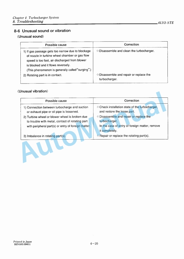
- 5.8.6. Unusual sound or vibration
- 6. CHAPTER 5.LUBRICATION SYSTEM
- 6.1. Lubrication System
- 6.2. Lube Oil Pump
- 6.2.1. Lube oil pump construction
- 6.2.2. Specifications of lube oil pump
- 6.2.3. Removal
- 6.2.4. Inspection
- 6.2.5. Instllation
- 6.3. Lube Oil Filter
- 6.3.1. Lube oil filter construction
- 6.3.2. Lube oil filter replacement
- 6.4. Oil Pressure Control Valve
- 6.4.1. Oil pressure control valve construction
- 6.4.2. Oil pressure control valve replacement
- 6.5. Lube Oil Cooler
- 6.5.1. Lube oil cooler construction
- 6.5.2. Inspecting the lube oil cooler
- 6.6. Piston Cooling Nozzle
- 6.6.1. Piston cooling nozzle construction
- 6.6.2. Inspection of piston cooling nozzle
- 6.7. Rotary Waste Oil Pump(Optional)
- 6.7.1. Construction
- 6.7.2. Inspection the waste oil pump
- 7. CHAPTER 6.COOLING WATER SYSTEM
- 7.1. Cooling Water System
- 7.1.1. System
- 7.1.2. Water leakage test(Fresh water)
- 7.1.3. Removing Scale(During Disassembly)
- 7.1.4. Anti-Corrosion Agent
- 7.1.5. Antifreeze
- 7.2. Sea Water Pump
- 7.2.1. Sea water pump construction and functioning
- 7.2.2. Sea water pump disassembly
- 7.2.3. Sea water pump inspection
- 7.2.4. Sea water pump reassembly
- 7.3. Fresh Water Pump
- 7.3.1. Fresh water pump construction
- 7.3.2. Specifications of fresh water pump
- 7.3.3. Fresh water pump disassembly
- 7.3.4. Fresh water pump reassembly
- 7.4. Fresh Water Cooler
- 7.4.1. Fresh water cooler construction
- 7.4.2. Specifications of heat exchanger
- 7.4.3. Disassembly and reassembly of the fresh water cooler
- 7.4.4. Fresh water cooler inspection
- 7.5. Pressure Cap and Sub Tank
- 7.5.1. Pressure cap construction
- 7.5.2. Pressure cap pressure control
- 7.5.3. Pressure cap inspection
- 7.5.4. Function of the sub tank
- 7.5.5. Specifications of sub tank
- 7.5.6. Mounting the sub tank
- 7.5.7. Precautions on usage of the sub tank
- 7.6. Thermostat
- 7.6.1. Functioning of thermostat
- 7.6.2. Thermostat construction
- 7.6.3. Characteristics of thermostat
- 7.6.4. Thermostat inspection
- 7.6.5. Testing the thermostat
- 7.7. Kingston Cock(Optional)
- 7.7.1. Construction
- 7.7.2. Handling precautions
- 7.7.3. Inspection
- 8. CHAPTER 7.REDUCTION AND REVERSING GEAR
- 8.1. Specification and System
- 8.1.1. Marine Gears(YANMAR MODEL KMH6A1)
- 8.2. Readdembly and disassembly(KMH6A1)
- 8.2.1. Disassembly
- 8.2.2. Disassembling input and output gears
- 8.2.3. Disassembling support shafts A and B
- 8.2.4. Disassembling valve body
- 8.3. Cautions for Reassembly
- 8.3.1. Cautions for Reassembly
- 8.3.2. Tightening Torque of Major Bolts
- 8.3.3. Standerd Tightening Torque
- 9. CHAPTER 8.REMOTO CONTROL(OPTIONAL)
- 9.1. Remoto Control System(Option)
- 9.1.1. Construction of remoto control system
- 9.1.2. Remoto control device components
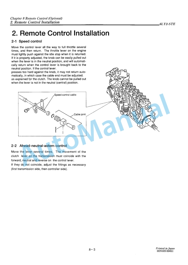
- 9.2. Remoto Control Installation
- 9.2.1. Speed control
- 9.2.2. Ahead-neutral-astern control
- 10. CHAPTER 9.ELECTRICAL SYSTEM
- 10.1. System Diagram
- 10.1.1. System diagram of electric parts
- 10.2. Battery
- 10.2.1. Construnctlon
- 10.2.2. Battery capacity and battery cables
- 10.2.3. Inspection
- 10.2.4. Charging
- 10.2.5. Battery storage precautions
- 10.3. Starter Motor
- 10.3.1. Specifications and Performance
- 10.3.2. Features
- 10.3.3. Construction
- 10.3.4. Disassembly
- 10.3.5. Maintenance standerd
- 10.3.6. Inspection
- 10.3.7. Reassembly precautions
- 10.3.8. Adjustment and performance test
- 10.3.9. Testing
- 10.3.10. Troubleshooting
- 10.4. Alternator
- 10.4.1. Features
- 10.4.2. Specifications
- 10.4.3. Characteristics
- 10.4.4. Construction
- 10.4.5. Alternator functioning
- 10.4.6. Handling precautions
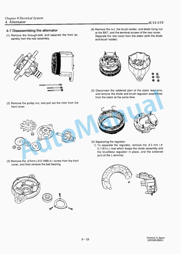
- 10.4.7. Disassembling the alternator
- 10.4.8. Inspection and adjustment
- 10.4.9. Reassembling the alternator
- 10.4.10. Performamce test
- 10.4.11. Troubleshooting
- 10.5. Instrument Panel
- 10.6. Warning Devices
- 10.6.1. Oil pressure alarm
- 10.6.2. Cooling water temperature alarm
- 10.6.3. Sender unit for lube pressure gauge
- 10.6.4. Sender unit for the cooling water temperature gauge
- 10.7. Tachometer
- 10.7.1. Construction of tachometer
- 10.7.2. Specifications and dimensions of tachometer
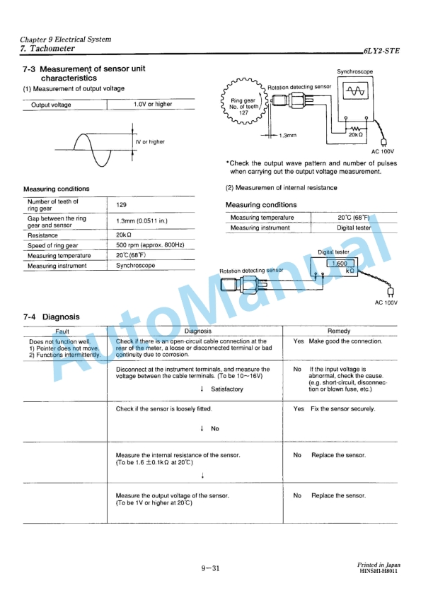
- 10.7.3. Measurement of sensor unit characteristics
- 10.7.4. Diagnosis
- 11. CHAPTER 10.DISASSEMBLY AND REASSEMBLY
- 11.1. Disassembly and Reassembly precautions
- 11.2. Disassembly and Reassembly Tools
- 11.2.1. Special Handtools
- 11.2.2. Measuring Instruments
- 11.2.3. Other material
- 11.3. Disassembly and Reassembly
- 11.3.1. Disassembly
- 11.3.2. Reassembly
- 11.4. Main parts spec./ tightening torque
- 11.4.1. Quality control points
- 11.4.2. Dimension of Main Parts
- 11.4.3. Bolt/Nut Tightening torque
- 11.5. Test running
- 11.5.1. Preliminary Precautions
- 11.5.2. Check Points and Precautions During Running
- 12. CHAPTER 11.TROUBLESHOOTING
- 12.1. Troubleshooting
- 13. BACK COVER


,%202GM20(F)(C),%203GM30(F)(C),%203HM35(F)(C)%20Marine%20Diesel%20Engine%20Service%20Manual&url=https://pdfrepairmanual.com/docs/yanmar-1gm10c-2gm20fc-3gm30fc-3hm35fc-marine-diesel-engine-service-manual/&media=https://pdfrepairmanual.com/wp-content/uploads/2026/01/yanmar-1gm10c-2gm20fc-3gm30fc-3hm35fc-marine-diesel-engine-service-manual-1.jpg)


,%202GM20(F)(C),%203GM30(F)(C),%203HM35(F)(C)%20Engine%20Service%20Manual&url=https://pdfrepairmanual.com/docs/yanmar-1gm10c-2gm20fc-3gm30fc-3hm35fc-engine-service-manual/&media=https://pdfrepairmanual.com/wp-content/uploads/2026/01/yanmar-1gm10c-2gm20fc-3gm30fc-3hm35fc-engine-service-manual-1.jpg)


There are no reviews yet.