
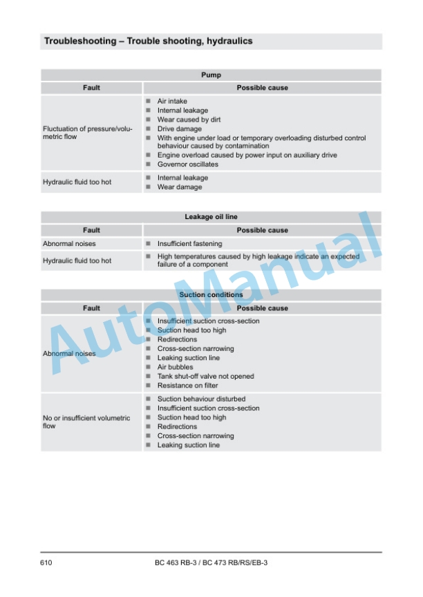
Description
-
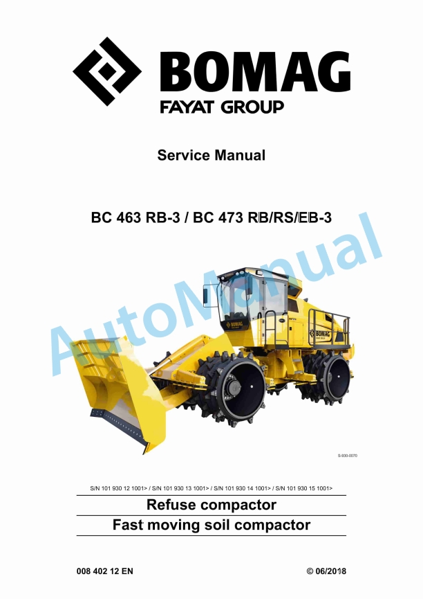
Model List:
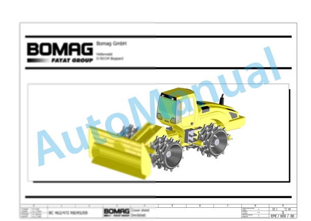
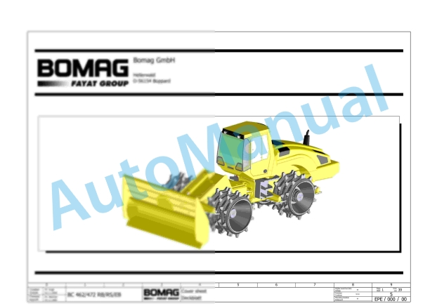
- BC 463 RB-3 Refuse Compactor
- BC 473 RB-3 Refuse Compactor
- BC 473 RS-3 Refuse Compactor
- BC 473 EB-3 Refuse Compactor
- 1. Table of contents
- 2. General
- 2.1. Introduction
- 2.2. Concerning your safety
- 2.2.1. Basic prerequisites
- 2.2.2. Definition of responsible persons
- 2.2.3. Fundamentals for safe operation
- 2.2.4. Handling fuels and lubricants
- 2.2.5. Loading / transporting the machine
- 2.2.6. Start up procedure
- 2.2.7. Driving the machine working operation
- 2.2.8. Refuelling
- 2.2.9. Emergency procedures
- 2.2.10. Maintenance work
- 2.2.11. Repair
- 2.2.12. Signage
- 2.3. Maintenance and repair
- 2.3.1. Notes on repair
- 2.3.2. Preliminary remarks and safety notes
- 2.3.3. Preparations / concluding work
- 2.3.4. Parking the machine in secured condition
- 3. Technical data
- 3.1. Technical data, BC 463 RB 3
- 3.1.1. Technical data
- 3.2. Technical data, BC 473 RB 3
- 3.2.1. Technical data
- 3.3. Technical data, BC 473 RS 3
- 3.3.1. Technical data
- 3.4. Technical data, BC 473 EB 3
- 3.4.1. Technical data
- 3.5. Additional technical data
- 3.6. Terms and basis of calculation
- 3.7. Fuels and lubricants
- 3.7.1. Engine oil
- 3.7.2. Fuel
- 3.7.3. Coolant
- 3.7.4. Hydraulic oil
- 3.7.5. Gear oil SAE 80W140
- 3.7.6. Lubrication grease
- 3.8. List of fuels and lubricants
- 4. Overview of machine
- 4.1. General information
- 4.2. Electric systems
- 4.3. Hydraulic system
- 4.4. Machine assemblies
- 4.4.1. Diesel engine
- 4.4.2. Air conditioning
- 4.4.3. Central lubrication system
- 4.4.4. Overview of maintenance flaps and doors
- 5. Electric systems
- 5.1. Basic principles
- 5.1.1. Measuring method
- 5.1.2. Understanding circuit diagrams
- 5.1.3. Telemecanique switch
- 5.1.4. Deutsch plug, series DT and DTM
- 5.1.5. Magnetic coil plug
- 5.1.6. Clipon technology
- 5.2. Overview of electric system
- 5.2.1. Operators stand
- 5.2.2. Wiring
- 5.2.3. CAN BUS overview
- 5.2.4. Table of fuels and lubricants
- 5.3. Starting the engine with jump leads
- 5.4. Installation locations of control units
- 5.5. Fuse assignment
- 5.5.1. Notes on safety
- 5.5.2. Central electrics
- 5.5.3. Main fuses
- 5.5.4. Control console cabin
- 5.6. Description of electrical components
- 5.6.1. Control console cabin
- 5.6.2. Control unit for air conditioning, A72
- 5.7. Training of electric system
- 5.8. Inspection and maintenance work
- 5.8.1. Maintenance Table
- 5.8.2. Every 500 operating hours
- 5.8.3. As required
- 6. Hydraulic system
- 6.1. Basic principles
- 6.1.1. Open and closed hydraulic circuit
- 6.1.2. Swash plate principle, pump
- 6.1.3. Swash plate principle, motor
- 6.1.4. External gear pumps
- 6.2. Overview of hydraulics
- 6.3. Description of hydraulic components
- 6.3.1. Travel pump, A4VG110 DA
- 6.3.2. Fan pump, A4VG56 EFEP
- 6.3.3. Steering and working pump, A10VO/VSO
- 6.3.4. Travel motor, A6VM HA2T
- 6.3.5. Fan motor
- 6.4. Description of hydraulic circuits
- 6.4.1. Charge circuit, engine hood, brake and travel speed range selection
- 6.4.2. Travel system
- 6.4.3. Cooling system
- 6.4.4. Working hydraulics
- 6.5. Inspection and maintenance work
- 6.5.1. Maintenance Table
- 6.5.2. Checks prior to start up
- 6.5.3. Every 500 operating hours
- 6.5.4. Every 1000 operating hours
- 6.5.5. Every 2000 operating hours
- 7. Machine assemblies
- 7.1. Diesel engine
- 7.1.1. Diesel engine description
- 7.1.2. Engine electrics
- 7.1.3. Inspection and maintenance work
- 7.2. Oscillating articulated joint
- 7.2.1. Repair overview
- 7.2.2. Repairing the articulated joint
- 7.2.3. Inspection and maintenance work
- 7.3. Compactor wheels and dozer blade
- 7.3.1. Inspection and maintenance work
- 7.4. Central lubrication system
- 7.4.1. Overview of central lubrication system
- 7.4.2. Technical description
- 7.4.3. Control board
- 7.4.4. Lubrication process
- 7.4.5. Progressive distributor
- 7.4.6. Lubrication oil pump
- 7.4.7. Inspection and maintenance work
- 7.5. Air conditioning
- 7.5.1. Overview of air conditioning
- 7.5.2. Control unit for air conditioning, A72
- 7.5.3. Physical principles
- 7.5.4. Refrigerant R134a
- 7.5.5. Compressor oil / refrigeration oil
- 7.5.6. Working principle of the air conditioning system
- 7.5.7. Monitoring devices
- 7.5.8. Description of components
- 7.5.9. Compressor
- 7.5.10. Emptying in case of repair
- 7.5.11. Drying and evacuation
- 7.5.12. Filling instructions
- 7.5.13. Steam table for R134a
- 7.5.14. Inspection and maintenance work
- 7.6. Auxiliary heating, AIRTRONIC
- 7.6.1. Description of function
- 7.6.2. Fuse assignment
- 7.6.3. Control panel
- 7.6.4. Inspection and maintenance work
- 8. Troubleshooting
- 8.1. Preliminary remarks
- 8.2. Emergency procedures
- 8.2.1. Actuating the emergency stop switch
- 8.2.2. Emergency exit
- 8.2.3. Disconnect the battery
- 8.2.4. Towing the machine
- 8.2.5. After towing
- 8.3. Troubleshooting, electrical systems
- 8.3.1. Preliminary remarks
- 8.3.2. Starting the engine with jump leads
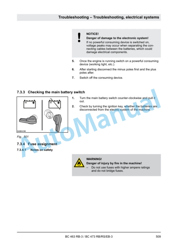
- 8.3.3. Checking the main battery switch
- 8.3.4. Fuse assignment
- 8.3.5. ESX, checking the electric power supply
- 8.3.6. Diagnostics concept
- 8.4. Trouble shooting, diesel engine
- 8.4.1. Engine faults
- 8.4.2. Starting the engine with jump leads
- 8.4.3. Operating the engine emergency mode
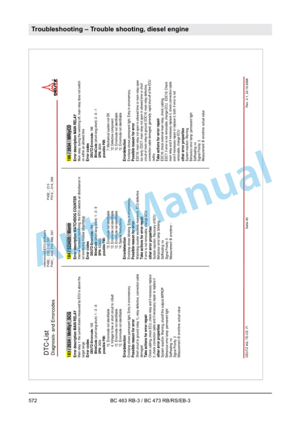
- 8.4.4. Deutz DTC fault code list, EMR3
- 8.5. Trouble shooting, hydraulics
- 8.5.1. Emergency operation of hood
- 8.5.2. Insufficient hydraulic power
- 8.5.3. Troubleshooting axial piston pumps
- 8.5.4. Troubleshooting axial piston motors
- 8.5.5. Troubleshooting table for hydraulic components
- 8.6. Troubleshooting, air conditioning system
- 8.6.1. Trouble shooting in refrigerant circuit, basic principles
- 8.6.2. Trouble shooting procedure
- 8.6.3. Leak test
- 8.6.4. Checking the magnetic clutch
- 8.7. Troubleshooting, central lubrication system
- 8.7.1. Function control
- 8.7.2. Faults and causes
- 8.7.3. Fault Cause Remedy
- 8.7.4. Failure of central lubrication system (grease emerges from relief valve)
- 8.8. Troubleshooting, auxiliary heating
- 8.8.1. Fuse assignment
- 8.8.2. Components
- 8.8.3. Control and safety elements
- 8.8.4. Trouble shooting
- 8.8.5. Diagnostics of control panel, old version
- 8.8.6. Diagnostics of control panel, new version
- 8.8.7. Check the fuel supply
- 8.8.8. Circuit diagram, AIRTRONIC D2/D4
- 9. Special tools
- 9.1. Special tools, electrics
- 9.2. List of special tools
- 10. Measures prior to extended shutdown period
- 10.1. Measures before shutting down
- 10.2. Battery service during prolonged machine downtimes
- 10.3. Measures before restarting
- 11. Index
- 12. Appendix
- 12.1. Appendices
- 12.2. A Circuit diagrams
- 12.2.1. Circuit diagram 382
- 12.2.2. Hydraulic diagram 571 908 27


There are no reviews yet.