
Description
-
Model List:
- BC 672 RB Refuse Compactor
- BC 672 RS Refuse Compactor
- BC 772 RB Refuse Compactor
- BC 772 RS Refuse Compactor
- 1. Contents
- 2. Foreword
- 3. Documentation
- 4. General
- 5. Maintenance
- 5.1. Maintenance table
- 6. List of components BC 672/772 RB
- 7. List of components BC 772 RS
- 8. Technical data and adjustment values
- 8.1. BC 672 RB
- 8.2. BC 772 RB
- 8.3. BC 772 RS
- 9. Deutz diesel engine
- 9.1. External engine components (starter side)
- 9.2. External attachments (generator side)
- 9.3. Lubrication oil diagram
- 9.4. Fuel prefilter / water separator (SEPARFilter)
- 9.4.1. Draining of water/fuel / regeneration of the filter element
- 9.5. Electronic engine control EMR
- 9.5.1. Individual EMR components
- 9.5.2. Fault diagnostics
- 9.5.3. EMR II from S/N 80 1039
- 9.5.4. Individual EMR II components
- 9.5.5. Control unit EMR II
- 9.5.6. Plug assignment X 5 and X 3
- 9.5.7. EMR II actuator Y 137
- 9.5.8. Coolant temperature sensor B 113
- 9.5.9. Speed sensors B 114 and B 130 on flywheel
- 9.5.10. Engine oil pressure sensor B88
- 9.5.11. Combined charge air pressure / temperature sensor B111 / B115
- 9.5.12. Fuel temperature sensor B 126
- 9.5.13. Selfdiagnostics (without operation of the diagnostics button)
- 9.5.14. Diagnostics with push button and fault code
- 9.5.15. Remedy
- 9.6. Adjusting the valve clearance
- 9.6.1. Designation of valves
- 9.7. Removing and installing the injection valves
- 9.8. Checking and adjusting the start of delivery
- 9.9. Replacing the radial seals on the entire engine
- 9.10. Replacing the thermostats
- 9.11. Replacing the coolant pump
- 9.12. Sealing / replacing the oil cooler
- 9.13. Replacing the cylinder head gasket
- 10. Hydraulic system
- 10.1. Travel system (general description)
- 10.1.1. Cooling of transfer box (from BC 672)
- 10.1.2. Travel pump
- 10.1.3. The closed circuit
- 10.1.4. Travel motors
- 10.1.5. Trouble shooting
- 11. Working hydraulics
- 11.1. Steering and working pump
- 11.2. Test and adjustment points on working pump
- 11.2.1. Check, adjust the high pressure
- 11.2.2. Checking the LSpressure to the working pumps
- 11.3. Control valve block for steering and dozer blade / bucket
- 11.4. Test and adjustment points, control valve block
- 11.5. Trouble shooting
- 12. Electric system
- 12.1. General
- 12.2. Table of potentials
- 12.3. Power supply (sheet 002)
- 12.4. Starting, preheating (sheet 003)
- 12.5. Engine speed control Deutz EMR (sheet 004)
- 12.6. Gauges (sheet 005)
- 12.7. Travel pumps, travel motors, start release (sheet 007)
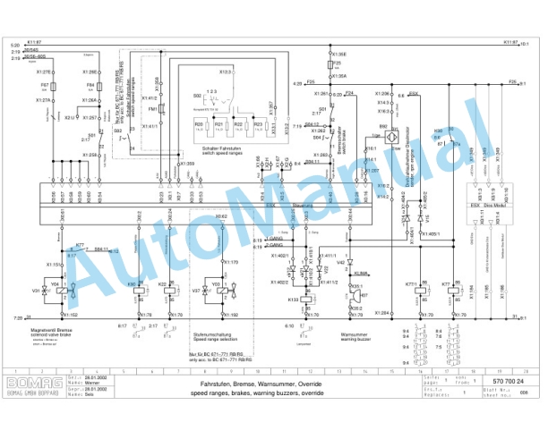
- 12.8. Travel speed ranges, brake, warning buzzer, override (sheet 008)
- 12.9. Travel speed range selector
- 12.10. Steering and dozer blade control (sheet 009)
- 12.11. Warning devices, lubrication system, seat adjustment and seat heating (sheet 010)
- 12.12. Heating and ventilation (sheet 011)
- 12.13. Safety ventilation, air conditioning (sheet 012)
- 12.14. Cabin and attachments, (sheet 013)
- 13. Lubrication system
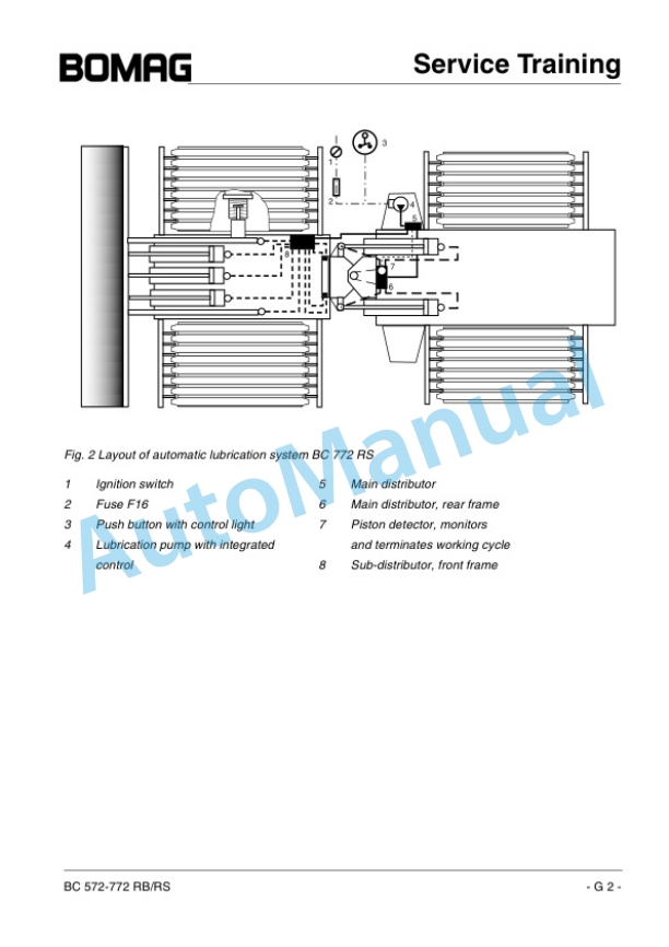
- 13.1. System design
- 13.2. Technical description
- 13.3. Function monitoring
- 13.4. Indication of faults
- 13.5. Description of components
- 13.6. Working mode of the pump element
- 13.7. The check valve
- 13.8. The pressure relief valve
- 13.9. Progressive distributor
- 13.10. Maintenance and tests
- 13.11. Trouble shooting
- 14. Climatronic
- 14.1. Physical principles
- 14.2. The boiling point
- 14.3. The refrigerant circuit
- 14.4. Description of the refrigerant circuit on BOMAG refuse compactors
- 14.5. Description of components
- 14.5.1. Compressor
- 14.5.2. Condensers
- 14.5.3. Liquid container with drier
- 14.5.4. Pressure switch (B75)
- 14.5.5. Block expansion valve
- 14.5.6. Evaporator
- 14.5.7. Thermostat icing protection (B 117)
- 14.5.8. Fan with rotational speed module
- 14.5.9. Climatronic control with control panel and components
- 14.6. General notes on repair and maintenance work
- 14.7. Emptying the air conditioning
- 14.8. Evacuating the air conditioning
- 14.9. Filling the air conditioning system
- 14.10. Technical data
- 15. Electric training (ESX)gbV4.00.pdf
- 15.1. Table of contents
- 15.2. Confirmation of changes
- 15.3. selected fault reactions of the ESX control
- 15.4. Known faults
- 15.5. Functions of the ESX control
- 15.5.1. Description of the display module
- 15.5.2. Input of code numbers
- 15.5.3. Driving against the closed brake
- 15.5.4. Simulate running engine
- 15.5.5. Enabling floating position
- 15.5.6. Showing stored faults
- 15.5.7. Deletes all stored faults
- 15.5.8. Adjusting the machine type
- 15.5.9. Parameter adjustment 2nd speed range (only BC972)
- 15.5.10. Parameter adjustment steering ( joystick / arm rest )
- 15.5.11. Parameter setting for travel pedal monitoring
- 15.6. Block diagram normal operation BC972
- 15.7. Block diagram normal operation BC 572/772
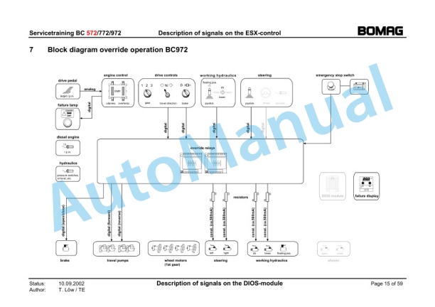
- 15.8. Block diagram override operation BC972
- 15.9. Block diagram override operation BC 572/772
- 15.10. Description of the signals on the ESXcontrol
- 15.11. Description of signals on the DIOS module (only with optional bucket)
- 15.12. Fault codes of the ESX control
- 15.12.1. Overview
- 15.12.2. Description of fault reactions
- 15.12.3. Detailed description of fault codes and their possible causes
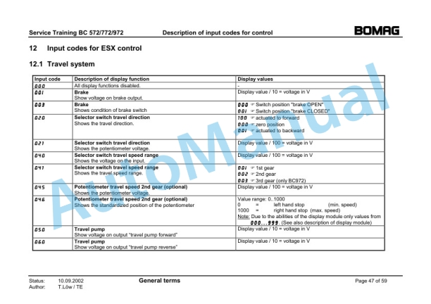
- 15.13. Input codes for ESX control
- 15.13.1. Travel system
- 15.13.2. Steering
- 15.13.3. Working hydraulics
- 15.13.4. Test functions
- 15.13.5. Diesel engine
- 15.13.6. System information
- 15.13.7. Hydraulics
- 15.13.8. Parameter change
- 15.13.9. Fault log
- 15.13.10. Setting the machine type
- 15.14. Terminology in connection with ESX
- 16. Electric circuit diagram EMR I
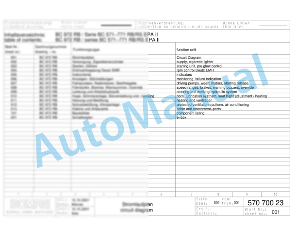
- 16.1. supply, cigarette lighter
- 16.2. starting unit, pre glow control
- 16.3. rpm control Deutz EMR
- 16.4. indicators
- 16.5. monitoring, failure indication
- 16.6. driving pumps, weehl motors, starting release
- 16.7. speed ranges, brakes, warning buzzers, override
- 16.8. steering and working hydraulic system
- 16.9. horn, lubrication systhem, seat hight adjustment / heating
- 16.10. heating and ventilation
- 16.11. protected ventilation systhem, air conditioning
- 16.12. cabin and attachmentparts
- 16.13. component listing
- 16.14. ebox
- 17. Electric circuit diagram EMR II until 12/03
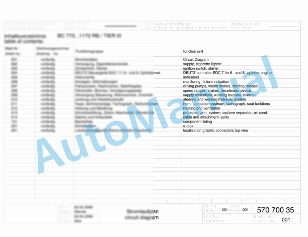
- 17.1. Circuit Diagram
- 17.2. supply, cigarette lighter
- 17.3. starting unit, heating flange
- 17.4. rpm control Deutz EMR
- 17.5. indicators
- 17.6. monitoring, failure indication
- 17.7. driving pumps, weehl motors, starting release
- 17.8. speed ranges, brakes, decelerator device
- 17.9. supply controllers, warning buzzers, override
- 17.10. steering and working hydraulic system
- 17.11. horn, lubrication systhem, seat hight adjustment / heating
- 17.12. heating and ventilation
- 17.13. protected ventilation system, air conditioning
- 17.14. cabin and attachmentparts
- 17.15. component listing
- 17.16. ebox
- 17.17. localization graphic connectors top view
- 18. Electric circuit diagram from 12/03
- 18.1. Circuit Diagram
- 18.2. supply, cigarette lighter
- 18.3. starting unit, heating flange
- 18.4. rpm control Deutz EMR
- 18.5. indicators
- 18.6. monitoring, failure indication
- 18.7. driving pumps, weehl motors, starting release
- 18.8. speed ranges, brakes, decelerator device
- 18.9. supply controllers, warning buzzers, override
- 18.10. steering and working hydraulic system
- 18.11. horn, lub. systhem, tachograph, seat hight adj. heating
- 18.12. heating and ventilation
- 18.13. protected ventilation system, air conditioning
- 18.14. cabin and attachmentparts
- 18.15. component listing
- 18.16. ebox
- 18.17. localization graphic connectors top view
- 19. Hydraulic schematics


There are no reviews yet.