
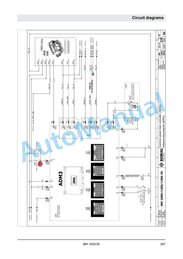
Description
-
Model List:
- BM 1000-35 Cold Planer
- 1. Table of contents
- 2. General
- 2.1. Introduction Service Manual
- 2.2. Concerning your safety
- 2.2.1. Handling fuels and lubricants
- 2.2.1.1. Preliminary remarks
- 2.2.1.2. Safety regulations and environmental protection regulations for handling diesel fuel
- 2.2.1.3. Safety regulations and environmental protection regulations for handling oil
- 2.2.1.4. Safety regulations and environmental protection regulations for handling hydraulic oil
- 2.2.1.5. Safety regulations and environmental protection regulations for handling coolants
- 2.2.1.6. Safety regulations and environmental protection regulations for handling battery acid
- 2.2.2. Working on hydraulic lines
- 2.2.3. Working on the engine
- 2.2.4. Maintenance work on electric components and battery
- 2.2.5. Working on heating elements
- 2.2.6. Cleaning work
- 2.2.7. Parking the machine in secured condition
- 2.3. Fuels and lubricants
- 2.3.1. Engine oil
- 2.3.1.1. Oil quality
- 2.3.1.2. Oil viscosity
- 2.3.1.3. Oil change intervals
- 2.3.2. Fuel
- 2.3.2.1. Fuel quality
- 2.3.2.2. Winter fuel
- 2.3.2.3. Storage
- 2.3.3. Coolant
- 2.3.3.1. General
- 2.3.3.2. Topping up coolant
- 2.3.3.3. Replacing coolant
- 2.3.4. Hydraulic oil
- 2.3.4.1. Mineral oil based hydraulic oil
- 2.3.4.2. Biodegradable hydraulic oil
- 2.3.5. Gear oil
- 2.3.6. Lubrication grease
- 2.3.7. Hightemperature lubrication grease
- 2.4. List of fuels and lubricants
- 2.5. Repair notes for hydraulics
- 3. Technical data
- 4. Total overview of machine
- 4.1. Component overview Electrics
- 4.2. Component overview hydraulics
- 5. Trouble shooting
- 5.1. Overviews
- 5.1.1. Overview Travel System
- 5.1.2. Overview Milling drive
- 5.1.3. Overview Height adjustment
- 5.1.4. Overview Steering
- 5.1.5. Overview Conveyor belt functions
- 5.1.6. Overview Swivelling the slewable chassis
- 5.2. Functional conditions
- 5.2.1. Functional conditions introduction
- 5.2.2. Functional conditions Starting the diesel engine
- 5.2.3. Functional conditions Shutting down the diesel engine
- 5.2.4. Functional conditions Release of travel lever
- 5.2.5. Functional conditions Activating transport speed
- 5.2.6. Functional conditions Activating working speed
- 5.2.7. Functional conditions Swivelling the track chain drive
- 5.2.8. Functional condition Switch on the milling drum
- 5.2.9. Functional condition Switch off the milling drum
- 5.2.10. Functional conditions Switch on conveyor belt
- 5.2.11. Functional conditions Switch off conveyor belt
- 5.2.12. Functional condition Moving the conveyor belt
- 5.2.13. Functional condition Unfolding and folding the conveyor belt
- 5.2.14. Functional conditions Activate/deactivate the differential lock
- 5.2.15. Functional conditions Scraper (all functions)
- 5.2.16. Functional conditions Holddown (all functions)
- 5.2.17. Functional conditions Side doors (left right) (all functions)
- 5.2.18. Functional conditions Lifting the machine
- 5.2.19. Functional conditions lowering the rear of the machine
- 5.2.20. Functional conditions Switching the water spraying system on/off
- 5.2.21. Functional conditions Switching the high pressure cleaner on/off
- 5.2.22. Functional conditions Switching the filling pump on/off
- 5.2.23. Functional conditions sunroof up/down
- 5.2.24. Functional conditions Opening/closing engine hood
- 5.2.25. Functional conditions Tool change
- 5.3. Fault codes
- 6. Electric systems
- 6.1. Control units
- 6.2. Display
- 6.2.1. Display General
- 6.2.2. Operating the extraction system
- 6.2.3. Operating the camera
- 6.2.4. Display Menu
- 6.2.4.1. Setting up the display
- 6.2.4.2. Menu option Diagnose
- 6.2.4.3. Menu option Service
- 6.2.4.3.1. Configuration
- 6.2.4.3.2. Service access
- 6.2.4.3.3. Actuator test
- 6.2.4.3.4. Executing teach procedures
- 6.3. Reserve wiring
- 7. Motor
- 7.1. General description
- 7.2. Engine electrics
- 7.2.1. Engine management MTU
- 7.2.2. Sensors MTU 6R 1000
- 7.3. Lubrication oil circuit
- 7.4. Cooling circuit
- 7.5. Fuel system
- 8. Hydraulic system
- 8.1. Component description
- 8.2. Travel pump
- 8.3. Conveyor belt pump
- 8.4. Fan pump
- 8.5. Working pump
- 8.6. Towing the machine
- 8.7. Trouble shooting axial piston pumps
- 9. Assembly groups
- 9.1. drive unit
- 9.1.1. Description
- 9.2. Milling unit
- 9.2.1. Description
- 9.3. Milling drum
- 9.3.1. Description
- 9.3.2. Repair
- 9.3.2.1. Checking the condition of cutting teeth and exchange holders
- 9.3.2.2. Replace the cutting chisels
- 9.3.2.3. Changing the milling drum
- 9.3.2.4. Change milling gear oil and filter
- 9.4. Conveyor unit
- 9.4.1. Description
- 9.4.2. Repair
- 9.4.2.1. Checking the conveyor belts
- 9.4.2.2. Tensioning the conveyor belt
- 9.4.2.3. Dismount the conveyor belt
- 9.4.2.4. Mounting the conveyor belt
- 9.5. Undercarriage
- 9.5.1. Description
- 9.5.2. Repair
- 9.6. Water system
- 9.6.1. Description
- 9.6.2. Operation
- 9.6.2.1. Checking the water level
- 9.6.2.1.1. Topping up water with the water pump
- 9.6.2.1.2. Topping up water from a hydrant
- 9.6.2.2. Topping up water with the water pump
- 9.6.2.3. Topping up water from a hydrant
- 9.7. Dust extraction
- 9.7.1. Description
- 10. Index
- 11. Appendix
- 11.1. Appendices
- 11.2. A Circuit diagrams
- 11.2.1. Electric circuit diagram
- 11.2.2. Hydraulic diagram 293


There are no reviews yet.