
Description
-
Model List:
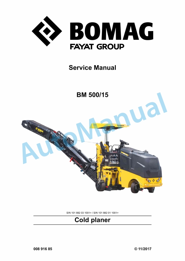
- BM 500-15 Cold Planer
- 1. Table of contents
- 2. General
- 2.1. Introduction
- 2.2. Concerning your safety
- 2.2.1. Basic prerequisites
- 2.2.2. Definition of responsible persons
- 2.2.3. Basic safety regulations for safe operation
- 2.2.4. Handling fuels and lubricants
- 2.2.5. Loading/transporting the machine
- 2.2.6. Startup procedure
- 2.2.7. Driving the machine, working operation
- 2.2.8. Refuelling
- 2.2.9. Emergency procedures
- 2.2.10. Maintenance work
- 2.2.11. Repair
- 2.2.12. Signage
- 2.3. Fuels and lubricants
- 2.3.1. Engine oil
- 2.3.2. Fuel
- 2.3.3. Coolant
- 2.3.4. Hydraulic oil
- 2.3.5. Gear oil ISO VG 220
- 2.3.6. Lubrication grease
- 2.3.7. Hightemperature lubrication grease
- 2.4. List of fuels and lubricants
- 2.5. Parking the machine in secured condition
- 3. Technical data
- 3.1. Noise and vibration data
- 3.1.1. Noise data
- 3.1.2. Vibration data
- 4. Overview of machine
- 4.1. Overview of electric system
- 4.2. Wiring
- 4.3. Overview of hydraulics
- 4.4. Overview of maintenance flaps and doors
- 5. Troubleshooting
- 5.1. Functional conditions
- 5.1.1. Functional conditions introduction
- 5.1.2. Functional conditions left side plate
- 5.1.3. Functional conditions right side plate
- 5.1.4. Functional conditions holddown
- 5.1.5. Functional conditions scraper
- 5.1.6. Functional conditions support wheel, rear left
- 5.1.7. Functional conditions support wheel, rear right
- 5.1.8. Functional conditions conveyor belt
- 5.1.9. Functional conditions milling
- 5.1.10. Functional conditions brake
- 5.2. Trouble shooting axial piston pumps
- 6. Electrics
- 6.1. Codes General Information
- 6.2. Error codes
- 6.2.1. Error code lists
- 6.3. Query codes
- 6.3.1. Query code lists
- 6.4. Input Codes
- 6.4.1. Display, layout and operation
- 6.4.2. Resetting to factory settings
- 6.4.3. Calibration of surge currents for height adjustment
- 6.4.4. Switching the unit system over
- 6.4.5. Water tank functions
- 6.4.6. Activation of relay in automatic mode
- 6.4.7. Conveyor belt ON via double and single buttons
- 6.4.8. Driving against the closed brake
- 6.4.9. Speed droop monitoring / display
- 6.4.10. Viscous fan
- 6.4.11. Software version
- 6.4.12. Milling clutch switching processes
- 6.4.13. Reversing with the milling drum switched ON
- 6.4.14. Showing the hydraulic oil temperature
- 6.4.15. 3way milling stage selector switch
- 6.4.16. Showing stored faults
- 6.4.17. Showing saved faults with operating hours
- 6.4.18. Deleting the error log
- 6.5. Replacement of components
- 6.6. Block diagrams
- 7. Diesel engine
- 7.1. Diesel engine description
- 7.1.1. Lubrication oil circuit
- 7.1.2. Cooling circuit
- 7.1.3. Fuel system
- 7.1.4. Common Rail
- 7.1.5. Exhaust gas recirculation
- 7.1.6. Wastegate charge pressure controller
- 7.1.7. Engine faults
- 7.2. Engine electrics
- 7.2.1. EMR3 system components
- 7.2.2. Pin assignment of engine control
- 7.2.3. Rotary speed sensor for camshaft, B114
- 7.2.4. Crankshaft speed sensor, B130
- 7.2.5. Rail pressure sensor, B93
- 7.2.6. Fuel pressure sensor, B145
- 7.2.7. Fuel Control Unit Y137
- 7.2.8. Injectors, Y147, Y149, Y169 and Y170
- 7.2.9. Oil pressure sensor, B88
- 7.2.10. Charge air temperature/charge pressure sensor, B133
- 7.2.11. EMRcoolant temperature sensor, B113
- 7.2.12. Glow plugs, R81R84
- 7.2.13. Sensor for water in fuel, B124
- 7.2.14. Air filter vacuum switch, B03
- 7.2.15. Float switch, coolant tank, B55
- 7.2.16. Diagnostics interface
- 7.2.17. Diagnose with Serdia
- 7.2.18. Diagnostics with CANbus
- 7.2.19. Deutz DTC error code list, EMR3
- 7.2.20. Removing and installing the electric starter
- 7.3. Inspection and maintenance work
- 7.3.1. Maintenance Table
- 7.3.2. Checks prior to start up
- 7.3.3. Every 250 operating hours
- 7.3.4. Every 500 operating hours
- 7.3.5. Every 1000 operating hours
- 7.3.6. Every 2000 operating hours
- 7.3.7. Every 3000 operating hours
- 7.3.8. Every 6000 operating hours
- 7.3.9. As required
- 8. Hydraulic system
- 8.1. Component overview hydraulics
- 8.2. Description of components
- 8.3. Repairs
- 8.3.1. Changing gear pumps on auxiliary drive of diesel engine
- 8.4. Inspection and maintenance work
- 8.4.1. Maintenance Table
- 8.4.2. Checks prior to start up
- 8.4.3. Every 250 operating hours
- 8.4.4. Every 500 operating hours
- 8.4.5. Every 1000 operating hours
- 8.4.6. Every 2000 operating hours
- 9. Assembly groups
- 9.1. Drive unit
- 9.1.1. Description
- 9.1.2. Repair
- 9.2. Milling drum
- 9.2.1. Description
- 9.2.2. Repair
- 9.3. Milling housing
- 10. Tests and adjustments
- 10.1. Special tools, hydraulic system
- 10.1.1. Special tools, tests and adjustments
- 10.1.2. Special tools for flushing
- 10.2. Checking and adjusting the levelling
- 10.3. Checking and adjusting the roof adjustment
- 10.4. Checking and adjusting the clutch operating pressure
- 10.5. Checking and adjusting the brake releasing pressure
- 10.6. Checking and adjusting the steering pressure
- 10.7. Working hydraulics Checking and adjusting the pressure MP
- 10.8. Checking and adjusting the scraper pressure
- 10.9. Checking and adjusting the conveyor belt pressure
- 10.10. Checking and adjusting the hydraulic breaker pressure
- 10.11. Checking and adjusting the maximum pressure of the travel pump
- 11. Special tools
- 11.1. Special tools, electrics
- 11.2. Special tools, hydraulic system
- 11.2.1. Special tools, tests and adjustments
- 11.2.2. Special tools for flushing
- 11.3. List of special tools
- 12. Index
- 13. Appendix
- 13.1. Appendices
- 13.2. A Circuit diagram 72
- 13.3. B Circuit diagram 77
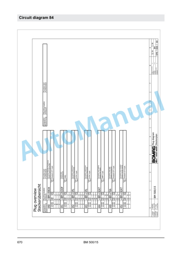
- 13.4. C Circuit diagram 84
- 13.5. D Circuit diagram 98
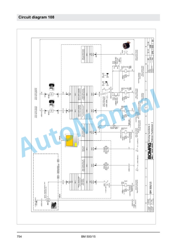
- 13.6. E Circuit diagram 108
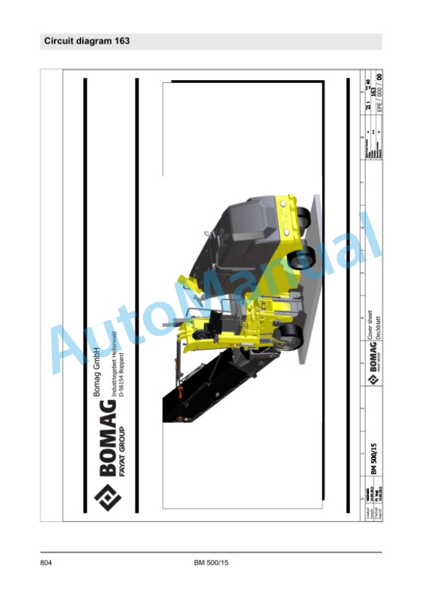
- 13.7. F Circuit diagram 163
- 13.8. G Wiring diagram 268
- 13.9. H Circuit diagram 295
- 13.10. I Hydraulic diagram 343


There are no reviews yet.