
Description
-
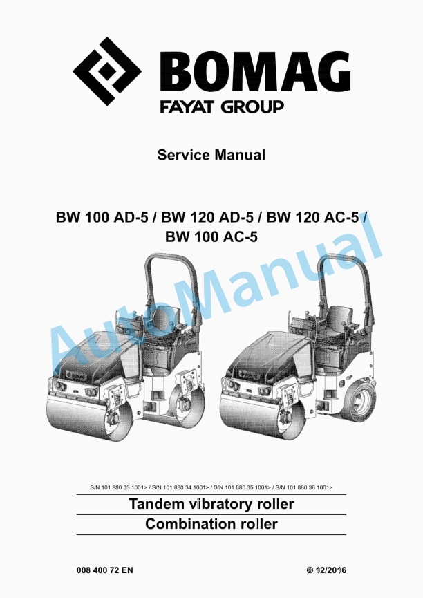
Model List:
- BW 100 AD-5 Tandem Vibratory Roller
- BW 100 AC-5 Tandem Vibratory Roller
- BW 120 AD-5 Tandem Vibratory Roller
- BW 120 AC-5 Tandem Vibratory Roller
- 1. Table of contents
- 2. General
- 2.1. Introduction
- 2.2. Concerning your safety
- 2.2.1. General prerequisites
- 2.2.2. Definition of responsible persons
- 2.2.3. Fundamentals for safe operation
- 2.2.4. Handling fuels and lubricants
- 2.2.5. Parking the machine in secured condition
- 2.2.6. Regeneration of exhaust gas aftertreatment system
- 2.2.7. What to do in events of emergency
- 2.2.8. Maintenance work
- 2.2.9. Repair
- 2.2.10. Decals , AD
- 2.2.11. Decals , AC
- 2.3. Notes on repair
- 2.3.1. General repair instructions
- 2.3.2. Tightening torques
- 2.4. Maintenance work
- 2.4.1. Preliminary remarks and safety notes
- 2.5. Fuels and lubricants
- 2.5.1. Fuels and lubricants
- 2.6. List of fuels and lubricants
- 2.6.1. List of fuels and lubricants
- 3. Technical data
- 3.1. BW 100 AD5
- 3.1.1. Technical data
- 3.2. BW 100 AC5
- 3.2.1. Technical data
- 3.3. BW 120 AD5
- 3.3.1. Technical data
- 3.4. BW 120 AC5
- 3.4.1. Technical data
- 3.5. Additional technical data
- 4. Overview of machine
- 4.1. Electric systems
- 4.2. Diesel engine
- 4.3. Hydraulic system
- 4.4. Drum
- 4.5. Oscillating articulated joint
- 4.6. Water spraying system
- 5. Electric systems
- 5.1. Overview of electric system
- 5.2. Table of fuels and lubricants
- 5.3. Wiring
- 5.4. CAN BUS overview
- 5.5. Central electrics
- 5.6. Fuse assignment
- 5.6.1. Notes on safety
- 5.6.2. Main battery fuse
- 5.6.3. Central electrics
- 5.7. Control elements
- 5.7.1. AD machine
- 5.7.2. AC machine
- 5.8. Battery service during prolonged machine downtimes
- 5.9. Starting the engine with jump leads
- 5.10. Generator repair
- 5.11. Starter
- 5.11.1. Repair of starter
- 5.11.2. Trouble shooting Starter
- 5.12. Instrument cluster (A15)
- 5.12.1. Fault code display
- 5.13. Seat contact control
- 5.14. Switching the vibration on
- 5.15. Switching on the pressure sprinkler system
- 5.16. Level sensor in diesel tank, R03
- 5.17. Sensor, water in fuel filter, B124
- 5.18. Charge control lamp and operating hour meter
- 5.19. Glow plugs, R81, R82 R83
- 5.20. Inductive proximity switch, B63
- 5.21. Angle sensor on travel control lever, B39
- 5.22. Telemecanique switch
- 5.23. Deutsch plug, series DT and DTM
- 5.24. Inspection and maintenance work
- 5.24.1. Maintenance Table
- 5.24.2. Every 250 operating hours
- 6. Diesel engine
- 6.1. Overview of diesel engine
- 6.2. CAN BUS overview
- 6.3. Features
- 6.4. Cooling system
- 6.5. Fuel system
- 6.6. Engine control
- 6.6.1. Fault code display
- 6.7. Exhaust gas recirculation, EGR
- 6.8. Exhaust gas aftertreatment
- 6.8.1. Fault code display
- 6.9. Regeneration of exhaust gas aftertreatment system
- 6.9.1. Preliminary remarks and safety notes
- 6.9.2. Suppressing regeneration
- 6.9.3. Running regeneration at standstill
- 6.10. Service specifications
- 6.11. Checking the engine oil pressure
- 6.12. Inspection and maintenance work
- 6.12.1. Maintenance Table
- 6.12.2. Checks prior to start up
- 6.12.3. Every 50 operating hours
- 6.12.4. Every 250 operating hours
- 6.12.5. Every 500 operating hours
- 6.12.6. Every 1000 operating hours
- 6.12.7. Every 2000 operating hours
- 6.12.8. Every 3000 operating hours
- 6.12.9. As required
- 7. Hydraulic system
- 7.1. Overview of hydraulics
- 7.2. Open and closed hydraulic circuit
- 7.3. Hydraulic units
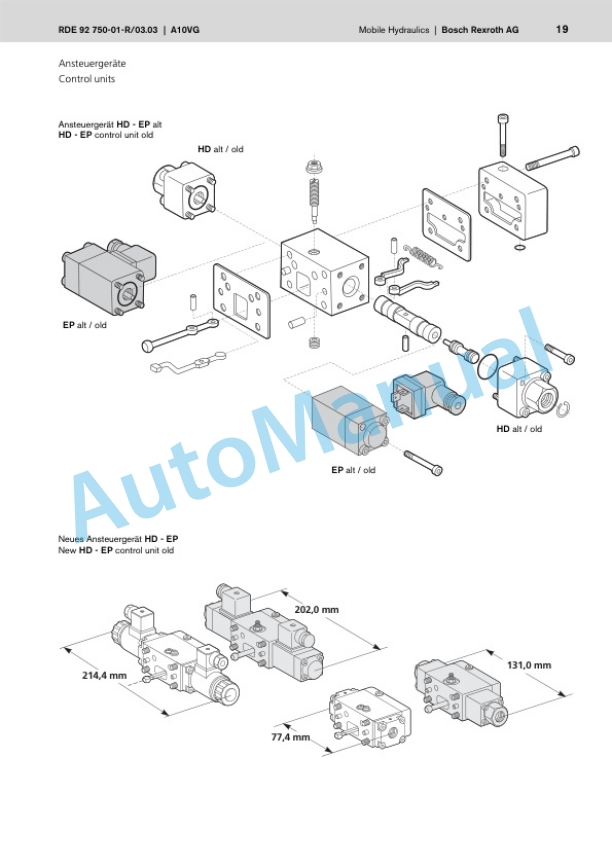
- 7.3.1. Travel pump, A10VG28 HW
- 7.3.2. Swash plate principle, pump
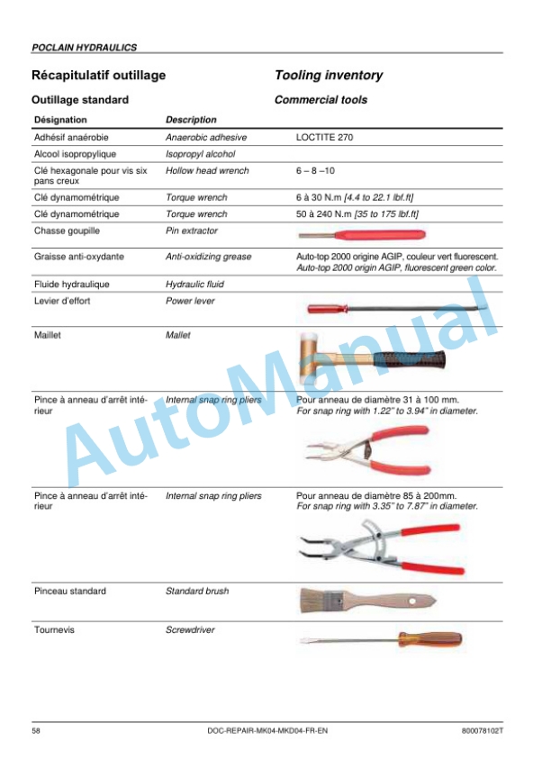
- 7.3.3. Drum drive motor MK 04
- 7.3.4. Wheel drive motor, MS/MSE
- 7.3.5. External gear pumps
- 7.3.6. Outer gear motors nonreversible
- 7.3.7. Steering valve
- 7.4. Charge circuit
- 7.5. Travel circuit
- 7.6. Vibration circuit
- 7.7. Steering circuit
- 7.8. Chip spreader
- 7.8.1. Mounting / removing the chip spreader
- 7.9. Edge cutter
- 7.9.1. Mounting the tool
- 7.10. Flow divider
- 7.11. Tests and adjustments
- 7.11.1. Checking the rotation speeds
- 7.11.2. Pressure tests in the travel circuit
- 7.11.3. Checking / adjusting the neutral positions of the travel pump
- 7.11.4. Pressure test in the vibration circuit
- 7.11.5. Checking the leakage rate of the vibration motor
- 7.11.6. Pressure test in steering circuit
- 7.12. Flushing and bleeding
- 7.12.1. Flushing general
- 7.12.2. Flushing diagram for front drum drive
- 7.12.3. Flushing the front drum drive
- 7.12.4. Flushing diagram for rear drum drive
- 7.12.5. Flushing the rear drum drive
- 7.12.6. Flushing diagram, rear wheel drive motors
- 7.12.7. Flushing the rear wheel drive
- 7.12.8. Flushing diagram for vibration drive on AD/SL machine
- 7.12.9. Flushing the vibration circuit
- 7.12.10. Bleeding the travel circuit
- 7.13. Inspection and maintenance work
- 7.13.1. Maintenance Table
- 7.13.2. Checks prior to start up
- 7.13.3. Every 500 operating hours
- 7.13.4. Every 1000 operating hours
- 7.13.5. Every 2000 operating hours
- 8. Drum
- 8.1. Edge cutter
- 8.1.1. Edge cutter
- 8.2. Overview drum
- 8.3. Removing and installing the drum
- 8.4. Dismantling the drum
- 8.5. Assembling the drum
- 9. Rubber tires
- 9.1. Inspection and maintenance work
- 9.1.1. Maintenance Table
- 9.1.2. Checks prior to start up
- 10. Scrapers
- 10.1. Inspection and maintenance work
- 10.1.1. Scrapers
- 10.1.2. Checks prior to start up
- 11. Oscillating articulated joint
- 11.1. Overview oscillating articulated joint
- 11.2. Disassembling the oscillating articulated joint
- 11.3. Repairing the oscillating articulated joint
- 11.4. Installing the oscillating articulated joint
- 12. Troubleshooting
- 12.1. Preliminary remarks
- 12.2. What to do in events of emergency
- 12.2.1. Actuating the emergency stop switch
- 12.2.2. Disconnecting the battery
- 12.2.3. Towing the machine
- 12.2.4. After towing, ADmachine
- 12.2.5. After towing, ACmachine
- 12.3. Troubleshooting, electrical systems
- 12.3.1. Preliminary remarks
- 12.3.2. Starting the engine with jump leads
- 12.3.3. Fuse assignment
- 12.3.4. Trouble shooting Starter
- 12.3.5. Instrument cluster (A15)
- 12.3.6. Trouble shooting ECONOMIZER
- 12.3.7. The machine does not drive
- 12.3.8. Seat contact control
- 12.3.9. Check the parking brake
- 12.3.10. Understanding electric circuit diagrams
- 12.3.11. Measuring method
- 12.4. Trouble shooting, hydraulics
- 12.4.1. Insufficient hydraulic power
- 12.4.2. Trouble shooting axial piston pumps
- 12.4.3. The machine does not drive
- 12.4.4. Insufficient travel power
- 12.4.5. Check the parking brake
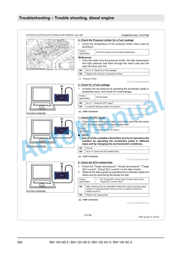
- 12.5. Trouble shooting, diesel engine
- 12.5.1. Fault code display
- 12.5.2. Diagnostics manual
- 13. Disposal
- 13.1. Final shutdown of machine
- 14. Special tools
- 14.1. Special tools, hydraulic system
- 14.1.1. Special tools, tests and adjustments
- 14.1.2. Special tools for flushing
- 14.2. Special tools, electrics
- 15. Index
- 16. Appendix
- 16.1. A Supplier documentation
- 16.1.1. Travel pump
- 16.1.2. Drum drive
- 16.1.3. Wheel drive
- 16.1.4. Steering valve
- 16.2. B Circuit diagrams
- 16.2.1. Hydraulic diagram 362
- 16.2.2. Circuit diagram 317


There are no reviews yet.