
Description
-
Model List:
- BW 135 AD Tandem Vibratory Roller
- BW 138 AD Tandem Vibratory Roller
- BW 138 AC Tandem Vibratory Roller
- 1. BW 135 AD / BW 138 AD / BW 138 AC
- 1.1. S/N 101 650 16 …. >S/N 101 650 17 …. >S/N 101 650 18 …. >
- 2. Tandem Vibratory Roller
- 3. Combination Roller
- 3.1. General
- 4. Introduction
- 5. Safety regulations
- 5.1. Important notes
- 5.2. General
- 5.3. Precautions and codes of conduct for welding work
- 5.4. Old oils
- 5.5. Hydraulics
- 5.6. Hot fuels
- 5.7. Synthetic rubber
- 5.8. Poisonous substances
- 5.9. Battery
- 5.10. Special safety regulations
- 6. General repair instructions
- 6.1. General
- 6.2. Electrics
- 6.3. Battery
- 6.4. Hydraulic system
- 6.5. Fuel hoses
- 6.6. Gaskets and mating surfaces
- 6.7. Feather keys and keyways
- 6.8. Ball and roller bearings
- 6.9. Screws and nuts
- 7. Tightening torques
- 7.1. Maintenance
- 8. General notes on maintenance
- 8.1. Notes on the fuel system
- 8.2. Notes on the engine performance
- 8.3. Notes on the hydraulic system
- 9. Fuels and lubricants
- 9.1. Engine oil
- 9.2. Oil viscosity
- 9.3. Regular lubrication oil changes
- 9.4. Oil quality
- 9.5. Lubrication oil change intervals
- 9.6. Lubrication oil quality classes
- 9.7. Winter fuel
- 9.8. Mineral oil based hydraulic oil
- 9.9. Biodegradable hydraulic oil
- 9.10. Lubrication grease
- 10. Table of fuels and lubricants
- 11. Runningin instructions
- 12. Maintenance chart
- 12.1. Technical data
- 12.2. Technical data
- 12.3. Fig. 11
- 12.4. Fig. 12
- 12.5. Noise value
- 12.6. Vibration value
- 13. Special tools, tests and adjustments
- 14. Checking the rotation speeds
- 14.1. Check the engine speed
- 14.2. Checking the exciter shaft speed
- 15. Pressure tests in the travel circuit
- 16. Checking / adjusting the neutral positions of the travel pump (Sauer pump)
- 17. Pressure tests in the vibration circuit
- 18. Checking the leakage rate of the vibration motor
- 19. Pressure test in steering circuit
- 20. General
- 20.1. General notes on trouble shooting in hydraulic systems
- 20.2. Important points for trouble shooting and fault rectification
- 21. Trouble shooting diagram
- 21.1. Fundamental electrics
- 21.2. Understanding circuit diagrams
- 21.3. Terminal designations
- 21.4. Current and voltage
- 21.5. Resistance
- 21.6. Series / parallel connection
- 21.7. Ohms law
- 21.8. Electrical energy
- 21.9. Formula diagram
- 21.10. Metrology
- 21.11. Diodes, relays, fuses
- 21.12. Batteries
- 21.13. Threephase generator
- 21.14. Electric starter
- 21.15. Telemecanique switch
- 21.16. Inductive proximity switches
- 21.17. Angle sensor with current output
- 21.18. Plug connectors
- 21.19. Deutsch plug, series DT and DTM
- 21.20. Plugs and terminals in spring clamping technology
- 22. Special tools, electrics
- 22.1. Fig. 10
- 22.2. Fig. 11
- 22.3. Fig. 12
- 22.4. Fig. 13
- 22.5. Fig. 14
- 22.6. Fig. 15
- 22.7. Fig. 16
- 22.8. Fig. 17
- 22.9. Fig. 18
- 22.10. Fig. 19
- 22.11. Fig. 20
- 22.12. Fig. 21
- 22.13. Fig. 22
- 22.14. Fig. 23
- 22.15. Fig. 24
- 22.16. Fig. 25
- 22.17. Fig. 26
- 22.18. Fig. 27
- 22.19. Fig. 28
- 22.20. Fig. 29
- 22.21. Fig. 30
- 22.22. Fig. 31
- 22.23. Fig. 32
- 22.24. Fig. 33
- 22.25. Fig. 34
- 22.26. Fig. 35
- 22.27. Fig. 36
- 22.28. Fig. 37
- 22.29. Fig. 38
- 22.30. Fig. 39
- 22.31. Fig. 40
- 22.32. Fig. 41
- 23. Vibration module
- 24. Module A68
- 24.1. Flushing and bleeding
- 25. Special tools for flushing
- 25.1. Fig. 10
- 25.2. Fig. 11
- 25.3. Fig. 12
- 25.4. Fig. 13
- 25.5. Fig. 14
- 25.6. Fig. 15
- 25.7. Fig. 16
- 25.8. Fig. 17
- 25.9. Fig. 18
- 25.10. Fig. 19
- 26. Flushing general
- 26.1. Changing a component
- 26.2. Chips (abrasion) in the oil
- 26.3. Before flushing
- 26.4. Bleeding
- 26.5. Servicing the flushing filter kit
- 27. Flushing schematic for front drum drive
- 27.1. Travel pump
- 27.2. Pipe joint (tool)
- 27.3. Reducing fitting (tool)
- 27.4. Connecting union (tool)
- 27.5. Rear drum drive motor
- 27.6. Flushing hose (tool) 20S 25S
- 27.7. Screw socket (tool) R1 25S
- 27.8. Flushing filter 1m (tool)
- 27.9. Front drum drive motor
- 27.10. Connecting union (tool)
- 27.11. Elbow union (tool)
- 27.12. Connecting union (tool)
- 27.13. Reducing fitting (tool)
- 27.14. High pressure hose
- 27.15. Flushing hose (tool) 20S 25S
- 28. Flushing the front drum drive
- 28.1. Fig. 10
- 29. Flushing schematic for rear drum drive system
- 29.1. Connecting union (tool)
- 29.2. Reducing fitting (tool)
- 29.3. Pipe joint (tool)
- 29.4. Rear drum drive motor
- 29.5. Flushing hose 20S 25S (tool)
- 29.6. Screw socket (tool) R1 25S
- 29.7. Flushing filter (tool)
- 29.8. Front drum drive motor
- 29.9. Connecting union (tool)
- 29.10. Reducing fitting (tool)
- 29.11. Elbow union (tool)
- 29.12. Connecting union (tool)
- 29.13. Travel pump
- 29.14. High pressure hose
- 29.15. Flushing hose 20S 25S (tool)
- 30. Flushing the rear drum drive
- 30.1. Fig. 10
- 31. Flushing schematic, rear wheel drive motors
- 31.1. Connecting union (tool)
- 31.2. Reducing fitting (tool)
- 31.3. Pipe joint (tool)
- 31.4. Rear wheel drive motors
- 31.5. Flushing hose 20S 25S (tool)
- 31.6. Screw socket (tool) R1 25S
- 31.7. Flushing filter 1m (tool)
- 31.8. Front drum drive motor
- 31.9. Connecting union (tool)
- 31.10. Reducing fitting (tool)
- 31.11. Elbow union (tool)
- 31.12. Connecting union (tool)
- 31.13. Travel pump
- 31.14. High pressure hose
- 31.15. Flushing hose 20S 25S (tool)
- 32. Flushing the rear wheel drive
- 32.1. Fig. 10
- 33. Flushing schematic for vibration drive
- 33.1. Screw fitting 3/4 15L (tool)
- 33.2. Flushing hose (tool)
- 33.3. Vibration valve
- 33.4. Vibration motor, rear (only ADmachine)
- 33.5. Vibration pump
- 33.6. Hydraulic oil tank
- 33.7. Front vibration motor
- 33.8. Connecting union (tool)
- 33.9. Flushing filter (tool)
- 33.10. Hydraulic hose
- 33.11. Flushing hose (tool)
- 34. Flushing the vibration circuit
- 35. Bleeding the travel circuit
- 36. Special tools
- 37. Repair overview for drum
- 38. Removing and installing the drum
- 38.1. Removing the drum
- 38.2. Installing the drum
- 39. Dismantling the drum
- 39.1. Removing the drum drive motor
- 39.2. Remove the vibration motor
- 39.3. Disassembling the bearing cover
- 39.4. Disassembling the exciter shaft
- 39.5. Dismantling the exciter shaft
- 39.6. Removing the cover
- 40. Assembling the drum
- 40.1. Installing the bearing cover
- 40.2. Assembling the exciter shaft
- 40.3. Installing the exciter shaft
- 40.4. Measuring the end float
- 40.5. Assembling the bearing plate
- 40.6. Installing the vibration motor
- 40.7. Installing the drum drive motor
- 41. Special tools, oscillating articulated joint (BW100/120 family)
- 42. Repair overview Oscillating articulated joint
- 42.1. Tensioning nut
- 42.2. Oscillation axle
- 42.3. Bearing housing
- 42.4. Carrier
- 42.5. Bearing block
- 42.6. Cylinder eye for steering cylinder
- 43. Removing and installing the oscillating articulated joint
- 44. Dismantling the oscillating articulated joint
- 44.1. Fig. 10
- 44.2. Fig. 11
- 45. Assembling the oscillating articulated joint
- 45.1. Fig. 10
- 45.2. Fig. 11
- 45.3. Fig. 12
- 45.4. Fig. 13
- 45.5. Fig. 14
- 45.6. Fig. 15
- 45.7. Fig. 16
- 45.8. Fig. 17
- 45.9. Fig. 18
- 45.10. Fig. 19
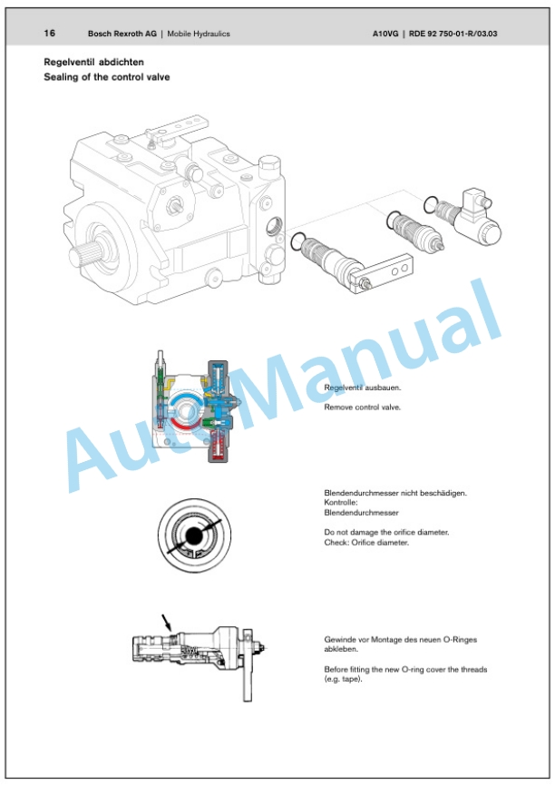
- 46. Travel pump A10VG28 ….63
- 47. Travel pump series 42
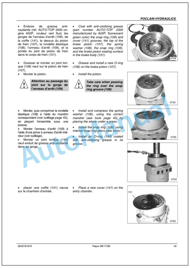
- 48. Drum drive MK05/08/11/18
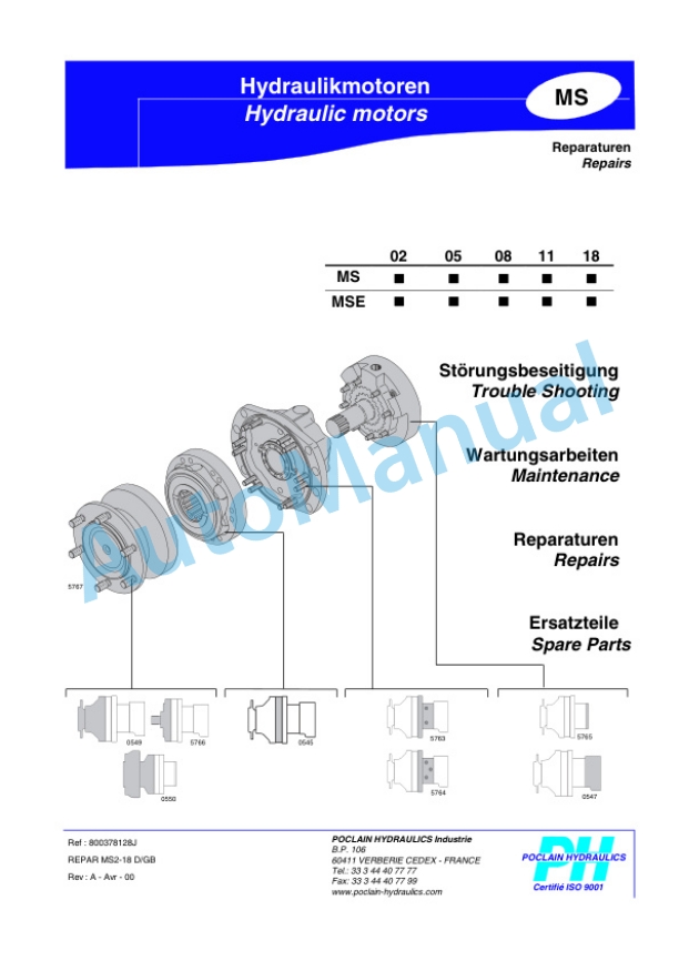
- 49. Wheel drive MS/MSE 02…18
- 49.1. Circuit diagrams
- 50. Wiring diagram
- 51. Wiring diagram
- 52. Hydraulic diagram
- 53. Hydraulic diagram
- 54. Hydraulic diagram


There are no reviews yet.