
Description
-
Model List:
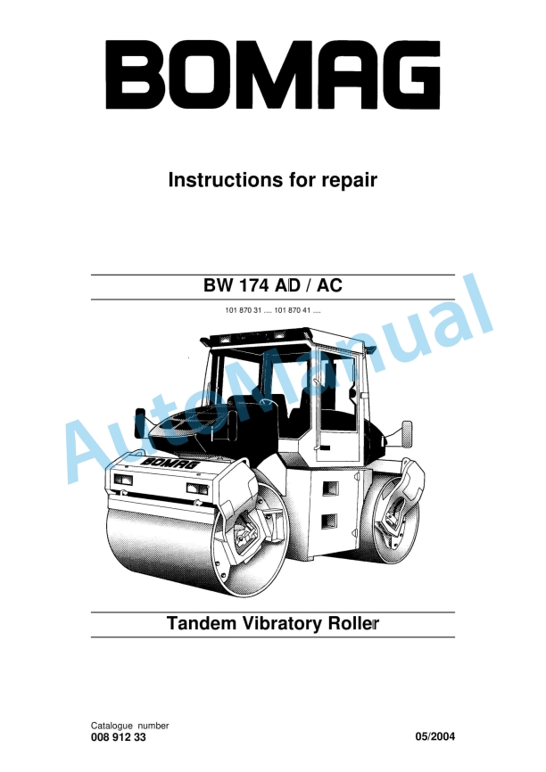
- BW 174 AD Tandem Vibratory Roller
- BW 174 AC Tandem Vibratory Roller
- 1. BW 174 AD / AC
- 1.1. … 101 870 41 ….
- 2. Tandem Vibratory Roller
- 2.1. General
- 3. Foreword
- 3.1. Introduction
- 4. Safety regulations
- 4.1. Important notes
- 4.2. General
- 4.3. Special safety regulations
- 4.4. Hydraulics
- 5. General repair instructions
- 5.1. General
- 5.2. Hydraulic system
- 5.3. Electrical system
- 5.4. Seals and gaskets
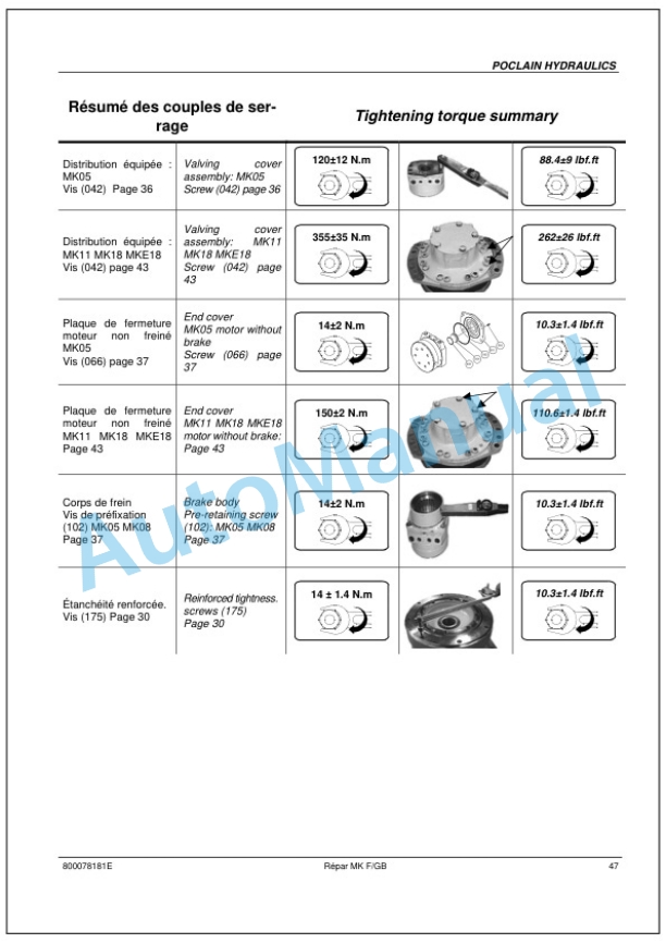
- 6. Tightening torques
- 6.1. Tightening torques
- 7. Connection overview
- 7.1. Fig. 1 Travel pump
- 7.2. Tests and adjustments
- 8. Technical data
- 9. Special tools
- 10. Checking the rotation speeds
- 10.1. Checking the engine speed
- 10.2. Checking the exciter shaft speed
- 11. Pressure tests in the travel circuit
- 12. Checking / adjusting the neutral positions of the travel pump
- 12.1. Mechanical neutral position
- 12.2. Hydraulic neutral position
- 13. Check the setting of the high pressure relief valves in the travel circuit
- 13.1. Adjusting the pressure override
- 14. Pressure measurements in the vibration circuit
- 15. Check the setting of the high pressure relief valves in the vibration circuit
- 15.1. Adjusting the pressure override
- 16. Checking / adjusting the vibrator shaft speeds
- 17. Checking the leakage rate of the vibration motor
- 18. Pressure test in steering circuit
- 18.1. Measuring the front steering pressure
- 18.2. Measuring the rear steering pressure
- 19. Operation of display module for ESX control
- 19.1. Description
- 19.2. Entering code numbers
- 20. Driving against the closed brake
- 21. Adjusting the machine type
- 22. Calibration of the angle transducers
- 22.1. Calibrating the front stops
- 22.2. Calibrating the rear stops
- 22.3. Calibrating the straight ahead position
- 23. Adjusting the angle transducers
- 23.1. Checking the front adjustment
- 23.2. Adjusting the angle transducer
- 23.3. Check the rear adjustment
- 24. Automatic detection of step currents for the steering valves
- 25. Adjusting the type of travel range switch
- 25.1. Adjusting the machine for the 24 stage switch
- 25.2. Adjusting the machine for the 3stage switch
- 26. Resetting the step currents in the travel system
- 27. Automatic detection of step currents in the travel system
- 27.1. Checking the function of the speed sensor
- 27.2. Detecting the step currents
- 28. Showing stored faults
- 28.1. Switching the function on
- 28.2. Switching the function off
- 29. Deleting stored faults
- 29.0.1. Flushing
- 30. Special tool
- 31. Flushing schematic for travel system
- 31.1. After changing a component
- 31.2. In case of excessive oil contamination (abrasion)
- 31.3. Befor flushing
- 31.4. Flushing filter installation (Fig. 1)
- 31.5. Flushing of the hoses
- 31.6. Flushing the complete system
- 31.7. Bleeding
- 32. Flashing the travel circuit
- 32.1. Cleaning the hydraulic oil tank
- 32.2. Filter installation for flushing the travel circuit
- 32.3. Bleeding the travel circuit
- 32.3.1. Fig. 10
- 32.4. Flushing the lines of the front travel circuit
- 32.4.1. Fig. 11
- 32.5. Flushing the lines of the rear travel circuit
- 32.5.1. Fig. 12
- 32.5.2. Fig. 13
- 32.6. Flushing the front drum drive motor
- 32.6.1. Fig. 14
- 32.6.2. Fig. 15
- 32.7. Flushing rear drum/wheel drive motors
- 32.7.1. Fig. 16
- 32.7.2. Fig. 17
- 32.8. Function test
- 32.8.1. Fig. 18
- 32.9. Servicing the flushing filter kit
- 33. Flushing schematic for vibration drive on ADmachines
- 33.1. After changing a component
- 33.2. In case of excessive oil contamination (abrasion)
- 33.3. Befor flushing
- 33.4. Flushing filter installation (Fig. 1)
- 33.5. Flushing of the hoses
- 33.6. Flushing the complete system
- 33.7. Bleeding
- 34. Flushing schematic for vibration drive on ACmachines
- 34.1. After changing a component
- 34.2. In case of excessive oil contamination (abrasion)
- 34.3. Befor flushing
- 34.4. Flushing filter installation (Fig. 1)
- 34.5. Flushing of the hoses
- 34.6. Flushing the complete system
- 34.7. Bleeding
- 35. Flushing the vibration circuit
- 35.1. Cleaning the hydraulic oil tank
- 35.2. Filter installation for flushing of the vibration drive
- 35.3. Bleeding the vibration circuit
- 35.4. Flushing the hoses in the vibration circuit
- 35.4.1. Fig. 10
- 35.5. Flushing the vibration motors
- 35.5.1. Fig. 11
- 35.5.2. Fig. 12
- 35.6. Function test
- 35.6.1. Fig. 13
- 35.7. Servicing the flushing filter kit
- 35.7.1. Trouble shooting
- 36. General
- 36.1. General notes on trouble shooting in hydraulic systems
- 36.2. Important points for trouble shooting and fault rectification
- 37. Trouble shooting diagram
- 37.1. The machine drives with the travel lever in NEUTRAL
- 37.2. Machine does not drive / insufficient travel performance
- 37.2.1. Charge pressure OK
- 37.2.2. Flushing valve OK
- 37.2.3. Nozzles OK
- 37.3. Hydraulic oil overheating >90 C
- 37.4. No vibration at front and rear Travel system O.K.
- 37.5. Speed of front and rear vibrator shafts too low
- 37.5.1. no, to high
- 37.6. No front steering steering sticky
- 37.7. No rear steering steering sticky
- 38. Special tools
- 39. Repair overview for drum
- 39.1. Fig. 1 Drum
- 40. Removing and installing the drum
- 40.1. Removal
- 41. Dismantling, assembling the drum
- 41.1. Dismantling
- 42. Dismantling, assembling the exciter shaft
- 42.1. Dismantling
- 43. Dismantling, assembling the change over weights
- 43.1. Dismantling
- 43.2. Assembly
- 43.2.0.1. Pivot steering
- 44. Removing, repairing and installing the pivot steering
- 44.1. Removal
- 45. Repairing the oscillation joint
- 45.1. Dismantling the oscillation joint
- 45.2. Assembling the oscillation joint
- 45.2.1. Fig. 10
- 45.2.2. Fig. 11
- 45.2.3. Fig. 12
- 45.2.4. Fig. 13
- 45.2.5. Fig. 14
- 45.2.6. Fig. 15
- 45.2.6.1. Suppliers documentation
- 46. MK 08
- 47. MS/MSE 02 to 18
- 48. A4VG
- 49. A10VG
- 50. A4FM28


There are no reviews yet.