
Description
-
Model List:
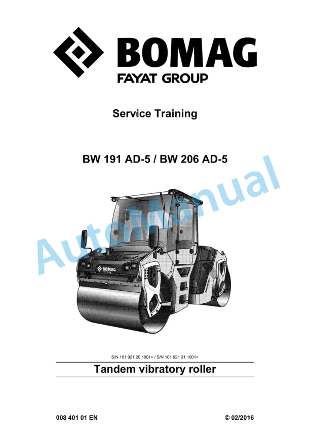
- BW 191 AD-5 Tandem Vibratory Roller
- BW 206 AD-5 Tandem Vibratory Roller
- 1. Table of contents
- 2. General
- 2.1. General
- 2.2. Concerning your safety
- 2.2.1. General prerequisites
- 2.2.2. Definition of responsible persons
- 2.2.3. Fundamentals for safe operation
- 2.2.4. Handling fuels and lubricants
- 2.2.5. Regeneration of exhaust gas aftertreatment system
- 2.2.6. What to do in events of emergency
- 2.2.7. Park the machine in secured condition.
- 2.2.8. Maintenance and repair
- 2.3. Fuels and lubricants
- 2.3.1. Fuels and lubricants
- 2.4. List of fuels and lubricants
- 2.4.1. List of fuels and lubricants
- 3. Technical data
- 3.1. Technical data, BW 191 AD5
- 3.1.1. Technical data
- 3.2. Technical data, BW 206 AD5
- 3.2.1. Technical data
- 3.3. Additional technical data
- 4. Overview of machine
- 4.1. Overview of electric system
- 4.2. Diesel engine
- 4.3. Overview of hydraulics
- 4.3.1. Pump overview
- 4.4. Overview of water spraying system
- 4.4.1. AD, ADO AM
- 4.4.2. Pump overview
- 4.5. Overview of air conditioning system
- 4.6. Overview, AD drum
- 4.7. Stickers and decals
- 5. Electric systems
- 5.1. Overview of electric system
- 5.2. Table of fuels and lubricants
- 5.3. Wiring
- 5.4. CAN BUS overview
- 5.5. Power board
- 5.6. Control console cabin
- 5.7. Fuse assignment
- 5.7.1. Notes on safety
- 5.7.2. Central electrics
- 5.7.3. Engine compartment
- 5.7.4. Fuse, cabin
- 5.7.5. Fuses ROPS
- 5.7.6. Fuses ROPS with swivel seat
- 5.8. Operators stand
- 5.8.1. Instrument cluster
- 5.9. Telemecanique switch
- 5.10. Deutsch plug, series DT and DTM
- 5.11. Servicing the battery, checking the main battery switch
- 5.11.1. Battery service
- 5.11.2. Checking the main battery switch
- 5.12. Starting the engine with jump leads
- 5.13. Electric steering wheel
- 5.14. Hydraulic cylinder with path measuring system
- 5.15. Asphalt temperature sensor, B106
- 5.16. Acceleration transducer, B84 B85
- 5.17. Switching on the pressure sprinkler system
- 5.18. Switching the emulsion sprinkling system on
- 5.19. Data collector, A80
- 5.20. Differential pressure switch for hydraulic oil filter, B21
- 5.21. Air filter vacuum switch, B03
- 5.22. Sensor, water in fuel filter, B124
- 5.23. Float switch, coolant compensation tank, B55
- 5.24. Charge control lamp
- 6. Diesel engine
- 6.1. Overview of diesel engine
- 6.2. Lubrication oil circuit TCD 4.1 / 6.1
- 6.3. Coolant circuit TCD 4.1 / 6.1
- 6.4. Common Rail System (CRS)
- 6.5. Wastegate charge pressure controller
- 6.6. Exhaust gas recirculation
- 6.7. EAT Exhaust Aftertreatment System
- 6.7.1. Selective Catalytic Reduction, SCR
- 6.7.2. Description of the SCR system components
- 6.7.3. SCR system warning strategy
- 6.8. DPFregeneration
- 6.8.1. Preliminary remarks and safety notes
- 6.8.2. Information codes
- 6.8.3. Suppressing DPFregeneration
- 6.8.4. Running regeneration at standstill
- 6.9. Engine electrics
- 6.9.1. CAN BUS overview
- 6.9.2. EMR4 system overview
- 6.9.3. EMR4 system components
- 6.10. Inspection and maintenance work
- 6.10.1. Maintenance Table
- 6.10.2. Checks prior to start up
- 6.10.3. Every 250 operating hours
- 6.10.4. Every 500 operating hours
- 6.10.5. Every 1000 operating hours
- 6.10.6. Every 2000 operating hours
- 6.10.7. Every 4000 operating hours
- 6.10.8. Every 6000 operating hours
- 6.10.9. As required
- 7. Hydraulic system
- 7.1. Overview of hydraulics
- 7.1.1. Pump overview
- 7.2. Open and closed hydraulic circuit
- 7.3. Hydraulic units
- 7.3.1. Travel pump, A4VG71 EP
- 7.3.2. Vibration pump, A10VG28 EP
- 7.3.3. Swash plate principle, pump
- 7.3.4. Drum drive motor
- 7.3.5. Vibration motor
- 7.3.6. External gear pumps
- 7.3.7. Outer gear motors nonreversible
- 7.3.8. Steering valve
- 7.4. Charge circuit and fan circuit
- 7.5. Travel circuit
- 7.6. Vibration circuit
- 7.7. Steering and crabwalk
- 7.8. Steering and crabwalk using slidable swivel seat
- 7.9. Edge cutter
- 7.10. Chip spreader
- 7.10.1. Mounting / removing the precision spreader
- 7.11. Tests and adjustments
- 7.11.1. Pump overview
- 7.11.2. Activate service mode
- 7.11.3. Driving against the closed brake
- 7.11.4. Pressure tests in the travel circuit
- 7.11.5. Checking / adjusting the neutral positions of the travel pump
- 7.11.6. Checking the setting of the high pressure relief valves in the travel circuit
- 7.11.7. Pressure tests in the front vibration circuit
- 7.11.8. Pressure tests in the rear vibration circuit
- 7.11.9. Checking the high pressure relief valves in the front vibration circuit
- 7.11.10. Checking the high pressure relief valves in the rear vibration circuit
- 7.12. Flushing and bleeding
- 7.12.1. Flushing general
- 7.12.2. Flushing diagram for front drum drive
- 7.12.3. Flushing the front drum drive
- 7.12.4. Flushing diagram for rear drum drive
- 7.12.5. Flushing the rear drum drive
- 7.12.6. Flushing diagram for front vibration drive
- 7.12.7. Flushing the front vibration circuit
- 7.12.8. Flushing diagram for rear vibration circuit
- 7.12.9. Flushing the rear vibration circuit
- 7.12.10. Bleeding the travel circuit
- 7.12.11. Bleeding the vibration circuit
- 7.13. Inspection and maintenance work
- 7.13.1. Maintenance Table
- 7.13.2. Check prior to start up
- 7.13.3. Every 500 operating hours
- 7.13.4. Every 1000 operating hours
- 7.13.5. Every 2000 operating hours
- 8. Water spraying system
- 8.1. Overview of water spraying system
- 8.1.1. AD, ADO AM
- 8.1.3. Pump overview
- 8.2. Inspection and maintenance work
- 8.2.1. Maintenance Table
- 8.2.2. Check prior to start up
- 8.2.3. As required
- 9. Air conditioning
- 9.1. Overview of air conditioning system
- 9.2. Physical principles
- 9.3. Refrigerant R134a
- 9.4. Compressor oil / refrigeration oil
- 9.5. Working principle of the air conditioning system
- 9.6. Monitoring devices
- 9.7. Description of components
- 9.8. Compressor
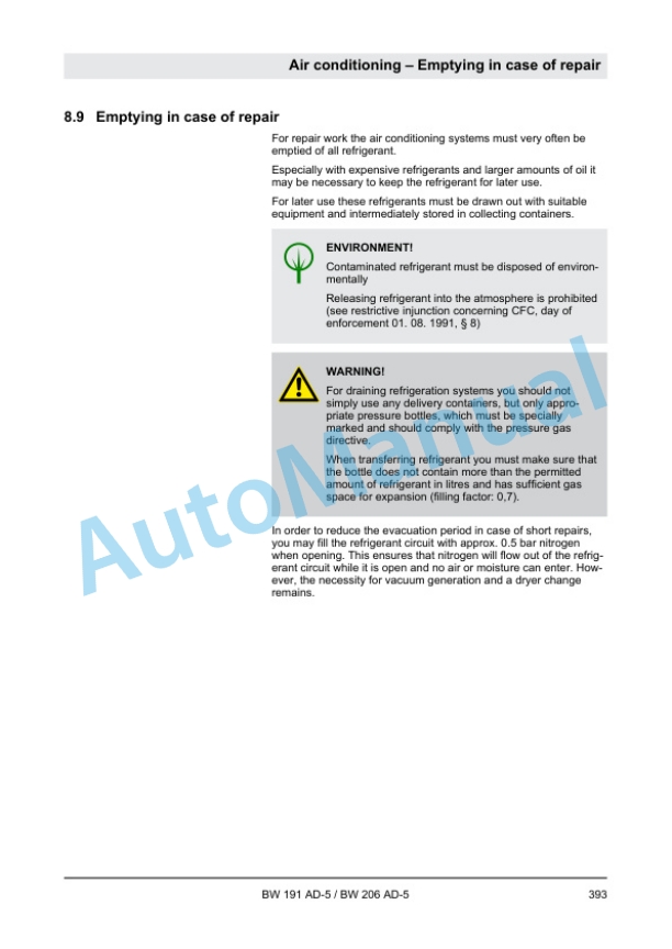
- 9.9. Emptying in case of repair
- 9.10. Drying and evacuation
- 9.11. Filling instructions
- 9.12. Steam table for R134a
- 9.13. Inspection and maintenance work
- 9.13.1. Maintenance Table
- 9.13.2. Every 250 operating hours
- 9.13.3. Every 500 operating hours
- 9.13.4. Every 1000 operating hours
- 9.13.5. As required
- 10. Drum
- 10.1. Overview, AD drum
- 10.2. Inspection and maintenance work
- 10.2.1. Maintenance Table
- 10.2.2. Check prior to start up
- 10.2.3. Every 500 operating hours
- 10.2.4. Every 1000 operating hours
- 11. Troubleshooting
- 11.1. Preliminary remarks
- 11.2. Emergency procedures
- 11.2.1. Actuating the emergency stop switch
- 11.2.2. Disconnecting the battery
- 11.2.3. Towing the machine
- 11.2.4. After towing
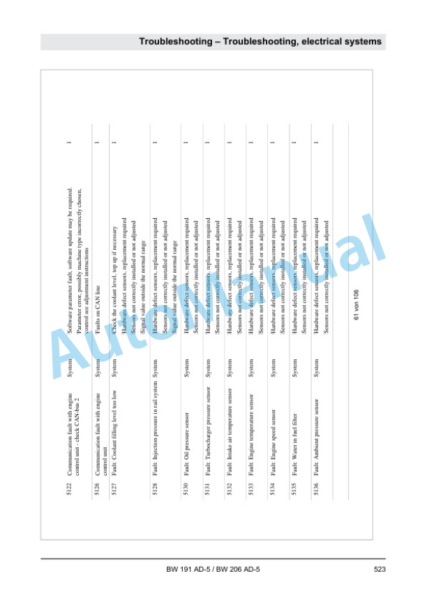
- 11.3. Troubleshooting, electrical systems
- 11.3.1. Preliminary remarks
- 11.3.2. Starting the engine with jump leads
- 11.3.3. Checking the main battery switch
- 11.3.4. Fuse assignment
- 11.3.5. Understanding electric circuit diagrams
- 11.3.6. Measuring method
- 11.3.7. ESX, checking the electric power supply
- 11.3.8. Diagnostics concept
- 11.3.9. Electrics training machine control
- 11.4. Trouble shooting, diesel engine
- 11.4.1. Starting the engine with jump leads
- 11.4.2. Engine faults
- 11.4.3. SCR system warning strategy
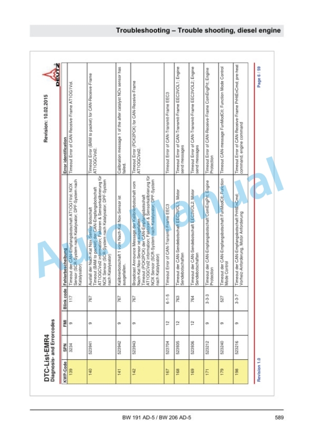
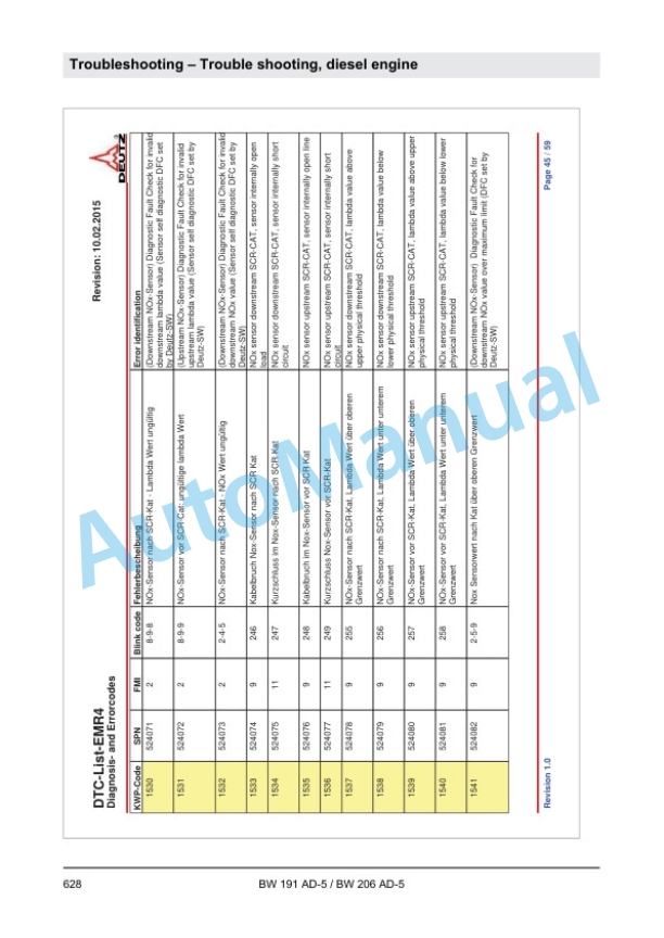
- 11.4.4. DTC error code list, EMR4
- 11.5. Trouble shooting, hydraulics
- 11.5.1. Insufficient hydraulic power
- 11.5.2. Trouble shooting axial piston pumps
- 11.5.3. Trouble shooting axial piston motors
- 11.6. Trouble shooting, air conditioning system
- 11.6.1. Trouble shooting in refrigerant circuit, basic principles
- 11.6.2. Trouble shooting procedure
- 11.6.3. Leak test
- 11.6.4. Checking the magnetic clutch
- 12. Special tools
- 12.1. Special tools, electrics
- 12.2. Special tools, hydraulic system
- 12.2.1. Special tools, tests and adjustments
- 12.2.2. Special tools for flushing
- 12.3. List of special tools
- 13. Index
- 14. Appendix
- 14.1. A Circuit diagrams
- 14.1.1. A Hydraulic diagram 921 130 76
- 14.1.2. B Wiring diagram 280


There are no reviews yet.