

Description
-
Model List:
- BW 211 D-3 Single Drum Wheel Drive Vibratory Roller
- 1. BW 211 D3
- 2. Single drum wheel drive vibratory roller
- 2.1. General
- 3. Foreword
- 3.1. Introduction
- 4. Safety regulations
- 4.1. Important notes
- 4.2. General
- 4.3. Special safety regulations
- 4.4. Hydraulics
- 5. General repair instructions
- 5.1. General
- 5.2. Hydraulic system
- 5.3. Electrical system
- 5.4. Seals and gaskets
- 6. Tightening torques
- 6.1. Tightening torques
- 7. Connecting plan
- 7.1. Fig. 1 Drive pump
- 7.2. Tests and adjustments
- 8. Technical Data
- 9. Special tools
- 10. Checking the rotary speeds
- 10.1. Checking the vibrator shaft speed
- 10.2. Checking the engine speed
- 11. Checking / adjusting the neutral positions of the travel pump
- 11.1. Mechanical neutral position
- 11.2. Hydraulic neutral position
- 12. Pressure tests in the travel circuit
- 13. Adjusting the high pressure relief valves in the travel system
- 13.1. Adjusting the pressure override
- 14. Adjusting the vibrator shaft speed
- 15. Pressure tests in the vibration circuit
- 16. Adjusting the high pressure relief valves in the vibration system
- 16.1. Adjusting the pressure override
- 17. Checking the leak oil rate of the vibration motor
- 18. Pressure tests in the steering circuit
- 18.0.1. Flushing
- 19. Special tools for flushing
- 20. Spülschema Fahrantrieb
- 20.1. After changing a component
- 20.2. With extreme oil contamination (abrasion)
- 20.3. Before flushing
- 20.4. Flushing filter installation (Fig. 1)
- 20.5. Flushing the hoses
- 20.6. Flushing the entire system
- 20.7. Bleeding
- 21. Flushing the travel circuit
- 21.1. Cleaning the hydraulic oil tank
- 21.2. Filter installation for flushing the travel system
- 21.3. Bleeding the travel circuit
- 21.4. Flushing the hoses in the travel circuit
- 21.5. Flushing the drum drive motor
- 21.5.1. Fig. 10
- 21.6. Flushing the axle drive motor
- 21.6.1. Fig. 11
- 21.7. Function test
- 21.7.1. Fig. 12
- 21.8. Maintenance of the flushing kit
- 22. Flushing diagram vibration circuit
- 22.1. After changing a component
- 22.2. In case of excessive oil contamination (abrasion)
- 22.3. Before flushing
- 22.4. Installation of the flushing filter (Fig. 1)
- 22.5. Flushing the hoses
- 22.6. Flushing the system
- 22.7. Bleeding
- 22.8. Function test
- 23. Flushing the vibration circuit
- 23.1. Cleaning the hydraulic oil tank
- 23.2. Filter installation for flushing the vibration system
- 23.3. Bleeding the vibration circuit
- 23.4. Flushing the hoses
- 23.5. Flushing the vibration motor
- 23.5.1. Fig. 10
- 23.6. Function test
- 23.6.1. Fig. 11
- 23.7. Maintenance of the flushing kit
- 23.7.1. Trouble shooting
- 24. General
- 24.1. General notes on trouble shooting in hydraulic systems
- 24.2. Important points for trouble shooting and fault rectification
- 25. Trouble shooting diagram
- 25.1. Steering pressure OK
- 25.2. Valve OK
- 25.3. High pressure OK
- 25.4. High pressure valves OK
- 25.5. Nozzles OK
- 25.6. Speed OK
- 25.7. Steering pressure OK
- 25.8. Valve OK
- 25.9. Pilot pressure OK
- 25.10. Voltage / current OK
- 25.11. High pressure OK
- 25.12. Valve OK
- 25.13. High pressure valves OK
- 25.14. Nozzles OK
- 25.15. Steering pressure OK
- 26. Special tools
- 27. Drum repair overview
- 28. Removing and installing the drum
- 28.1. Removing the drum
- 28.2. Installing the drum
- 28.2.1. Fig. 10
- 28.2.2. Fig. 11
- 28.2.3. Fig. 12
- 28.2.4. Fig. 13
- 28.2.5. Fig. 14
- 29. Repairing the drum
- 29.1. Removing the travel motor
- 29.2. Removing the vibrator unit (travel motor side)
- 29.3. Dismantling the vibrator unit (travel motor side)
- 29.3.1. Fig. 10
- 29.3.2. Fig. 11
- 29.3.3. Fig. 12
- 29.3.4. Fig. 13
- 29.3.5. Fig. 14
- 29.3.6. Fig. 15
- 29.3.7. Fig. 16
- 29.3.8. Fig. 17
- 29.3.9. Fig. 18
- 29.3.10. Fig. 19
- 29.3.11. Fig. 20
- 29.4. Removing the vibrator unit (vibration motor side)
- 29.4.1. Fig. 21
- 29.4.2. Fig. 22
- 29.4.3. Fig. 23
- 29.4.4. Fig. 24
- 29.4.5. Fig. 25
- 29.4.6. Fig. 26
- 29.4.7. Fig. 27
- 29.4.8. Fig. 28
- 29.5. Removing, dismantling the side
- 29.5.1. Fig. 29
- 29.5.2. Fig. 30
- 29.5.3. Fig. 31
- 29.5.4. Fig. 32
- 29.5.5. Fig. 33
- 29.5.6. Fig. 34
- 29.6. Dismantling the vibrator unit (vibration motor side)
- 29.6.1. Fig. 35
- 29.6.2. Fig. 36
- 29.6.3. Fig. 37
- 29.6.4. Fig. 38
- 29.6.5. Fig. 39
- 29.6.6. Fig. 40
- 29.6.7. Fig. 41
- 29.6.8. Fig. 42
- 29.6.9. Fig. 43
- 29.6.10. Fig. 44
- 29.6.11. Fig. 45
- 29.7. Assembling the vibrator unit (vibration motor side)
- 29.7.1. Fig. 46
- 29.7.2. Fig. 47
- 29.7.3. Fig. 48
- 29.7.4. Fig. 49
- 29.7.5. Fig. 50
- 29.7.6. Fig. 51
- 29.7.7. Fig. 52
- 29.7.8. Fig. 53
- 29.7.9. Fig. 54
- 29.7.10. Fig. 55
- 29.7.11. Fig. 56
- 29.7.12. Fig. 57
- 29.7.13. Fig. 58
- 29.7.14. Fig. 59
- 29.7.15. Fig. 60
- 29.7.16. Fig. 61
- 29.7.17. Fig. 62
- 29.7.18. Fig. 63
- 29.7.19. Fig. 64
- 29.7.20. Fig. 65
- 29.7.21. Fig. 66
- 29.7.22. Fig. 67
- 29.8. Assembling and installing the side plate
- 29.8.1. Fig. 68
- 29.8.2. Fig. 69
- 29.8.3. Fig. 70
- 29.8.4. Fig. 71
- 29.8.5. Fig. 72
- 29.8.6. Fig. 73
- 29.8.7. Fig. 74
- 29.8.8. Fig. 75
- 29.8.9. Fig. 76
- 29.8.10. Fig. 77
- 29.8.11. Fig. 78
- 29.8.12. Fig. 79
- 29.9. Assembling the vibrator unit (travel motor side)
- 29.9.1. Fig. 80
- 29.9.2. Fig. 81
- 29.9.3. Fig. 82
- 29.9.4. Fig. 83
- 29.9.5. Fig. 84
- 29.9.6. Fig. 85
- 29.9.7. Fig. 86
- 29.9.8. Fig. 87
- 29.9.9. Fig. 88
- 29.9.10. Fig. 89
- 29.9.11. Fig. 90
- 29.9.12. Fig. 91
- 29.9.13. Fig. 92
- 29.9.14. Fig. 93
- 29.9.15. Fig. 94
- 29.9.16. Fig. 95
- 29.9.17. Fig. 96
- 29.9.18. Fig. 97
- 29.10. Installing the vibrator unit (travel motor side)
- 29.10.1. Fig. 98
- 29.10.2. Fig. 99
- 29.10.3. Fig. 100
- 29.10.4. Fig. 101
- 29.10.5. Fig. 102
- 29.11. Installing the travel motor
- 29.11.1. Fig. 103
- 29.11.2. Fig. 104
- 29.11.3. Fig. 105
- 29.11.4. Fig. 106
- 29.12. Installing the vibrator unit (vibration motor side)
- 29.12.1. Fig. 107
- 29.12.2. Fig. 108
- 29.12.3. Fig. 109
- 29.12.4. Fig. 110
- 29.12.5. Fig. 111
- 29.12.6. Fig. 112
- 29.12.7. Fig. 113
- 29.12.8. Fig. 114
- 29.12.9. Fig. 115
- 29.12.10. Fig. 116
- 29.12.11. Fig. 117
- 30. Disassembling and assembling the changeover weight
- 30.1. Dismantling the changeover weight
- 30.2. Assembling the changeover weight
- 31. Changing the rubber buffers
- 31.0.1. Oscillating articulated joint
- 32. Special tools
- 33. Oscillating articulated joint repair
- 34. Removing and installing the oscillating articulated joint
- 35. Dismantling the oscillating articulated joint
- 36. Assembling the oscillating articulated joint
- 36.0.1. Suppliers documentation
- 37. Travel drive series 51
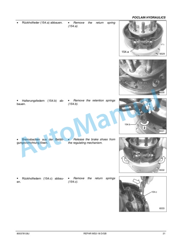
- 38. MS/MSE 02 to 18
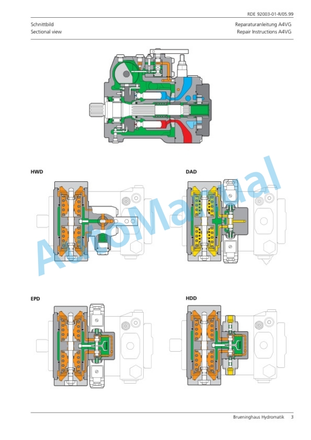
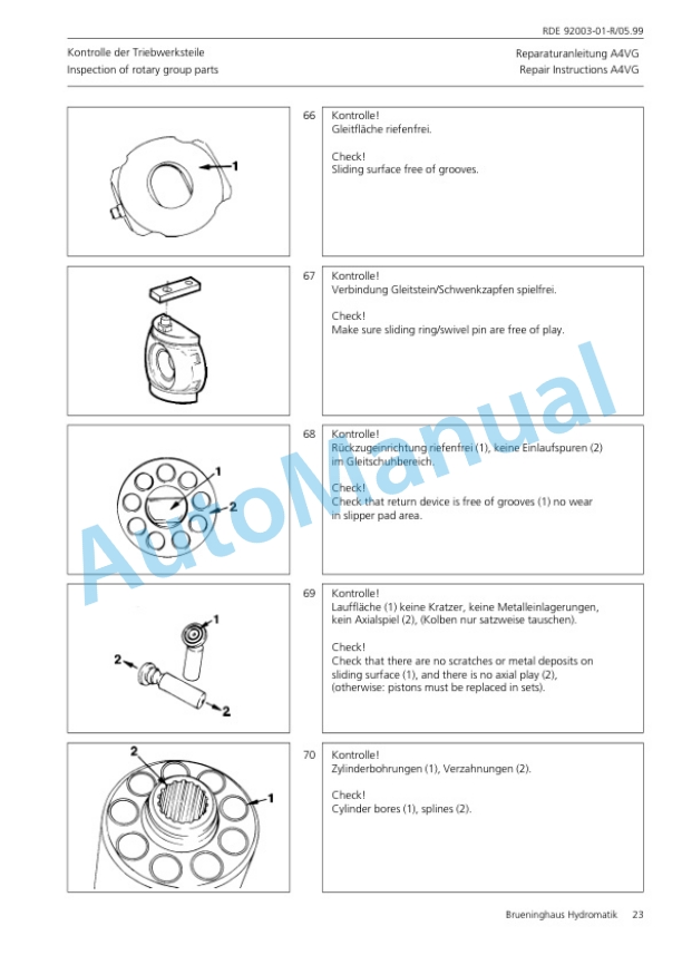
- 39. A4VG
- 40. A10VG


There are no reviews yet.