
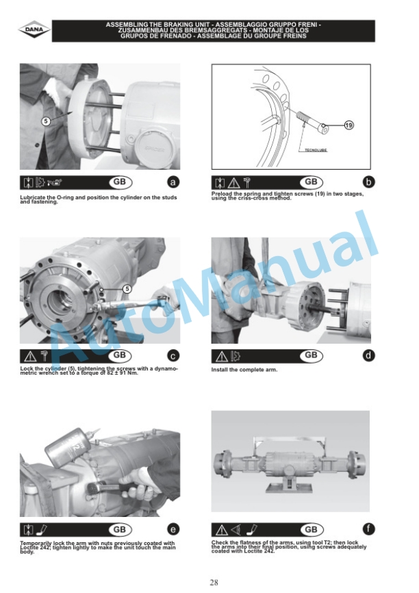
Description
-
Model List:
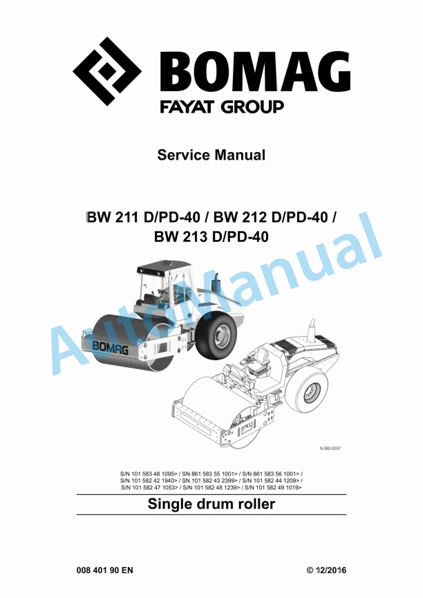
- BW 211 D-40 Single Drum Roller
- BW 211 PD-40 Single Drum Roller
- BW 212 D-40 Single Drum Roller
- BW 212 PD-40 Single Drum Roller
- BW 213 D-40 Single Drum Roller
- BW 213 PD-40 Single Drum Roller
- 1. Table of contents
- 2. General
- 2.1. Introduction
- 2.2. Concerning your safety
- 2.3. Notes on repair
- 2.4. Fuels and lubricants
- 2.5. List of fuels and lubricants
- 3. Overview of machine
- 3.1. Diesel engine
- 3.2. Travel / vibration pump
- 3.3. Drum
- 4. Technical data
- 4.1. Technical data BW 211 D/PD40
- 4.2. Technical data BW 212 D/PD40 (58243, 58248, 58356)
- 4.3. Technical data BW 212 D40 (58348, 58356)
- 4.4. Technical data BW 213 D/PD40
- 4.5. Additional technical data
- 5. Electric systems
- 5.1. Table of fuels and lubricants
- 5.2. Central electrics
- 5.3. Fuse assignment
- 5.4. Operators stand
- 5.5. Wiring
- 5.6. Starting the engine with jump leads
- 5.7. Proximity switches on travel lever, B13 and B14
- 5.8. Differential pressure switch for hydraulic oil filter, B21
- 5.9. Level sensor in diesel tank, R03
- 5.10. Float switch, coolant tank, B55
- 5.11. Air filter vacuum switch, B03
- 5.12. Sensor for water in fuel, B124
- 5.13. Fuel preheating, R79
- 5.14. Oil pressure switch, B06
- 5.15. Coolant temperature switch, B30
- 5.16. Boost fuel solenoid valve, Y01
- 5.17. Solenoid actuator to shut down the engine, Y13
- 5.18. Engine solenoid actuator, Y120
- 5.19. Charge control light, engine tachometer
- 5.20. Heating flange on engine, R19
- 5.21. MESSX, A83
- 5.22. Acceleration transducer, B62
- 5.23. Control unit for air conditioning, A108
- 5.24. Module for seat contact monitoring, A68
- 5.25. Vibration module, K04
- 5.26. Speedometer module, A05
- 5.27. Telemecanique switch
- 5.28. Deutsch plug, series DT and DTM
- 5.29. Magnetic coil plug
- 5.30. Inspection and maintenance work
- 6. Diesel engine
- 6.1. Diesel engine, general
- 6.2. Service side
- 6.3. Starter side
- 6.4. Lubrication oil circuit
- 6.5. Coolant circuit
- 6.6. Replacing the thermostat
- 6.7. Fuel supply
- 6.8. Injection system
- 6.9. Injection pump replacement during service
- 6.10. Injection valve replacement during service
- 6.11. Checking / repairing injection valves
- 6.12. Checking the compression
- 6.13. Inspection and maintenance work
- 7. Hydraulic system
- 7.1. Overview of travel/vibration pump connections
- 7.2. Open and closed hydraulic circuit
- 7.3. Hydraulic units
- 7.4. Charge circuit
- 7.5. Travel circuit
- 7.6. Vibration circuit
- 7.7. Steering circuit
- 7.8. Tests and adjustments
- 7.9. Flushing and bleeding
- 7.10. Inspection and maintenance work
- 8. Air conditioning
- 8.1. Overview
- 8.2. Physical principles
- 8.3. Refrigerant R134a
- 8.4. Compressor oil / refrigeration oil
- 8.5. Working principle of the air conditioning system
- 8.6. Monitoring devices
- 8.7. Description of components
- 8.8. Compressor
- 8.9. Emptying in case of repair
- 8.10. Drying and evacuation
- 8.11. Filling instructions
- 8.12. Steam table for R134a
- 8.13. Inspection and maintenance work
- 9. Cabin assembly before initial commissioning
- 9.1. Preparations
- 9.2. Cabin assembly
- 9.3. Final function tests and checks
- 10. Replacing the cab window panes
- 10.1. Assembly of window panes
- 10.2. Auxiliary materials
- 10.3. Removing and installing the window pane
- 11. Oscillating articulated joint
- 11.1. Overview oscillating articulated joint
- 11.2. Removing and installing the oscillating articulated joint
- 11.3. Dismantling the oscillating articulated joint
- 11.4. Assembling the oscillating articulated joint
- 12. Drum
- 12.1. Assembly of padfoot shell
- 12.2. Overview drum
- 12.3. Removing and installing the drum
- 12.4. Dismantling the drum
- 12.5. Dismantling and assembling the changeover weight
- 12.6. Assembling the drum
- 12.7. Changing the rubber buffers, adjusting the pretension
- 12.8. Inspection and maintenance work
- 13. Drive axle
- 13.1. Drive axle
- 13.2. Checks prior to start up
- 13.3. Every 250 operating hours
- 13.4. Every 1000 operating hours
- 13.5. As required
- 14. Troubleshooting
- 14.1. Preliminary remarks
- 14.2. Emergency procedures
- 14.3. Troubleshooting, electrical systems
- 14.4. Troubleshooting, diesel engine
- 14.5. Trouble shooting, hydraulics
- 14.6. Trouble shooting, air conditioning system
- 15. Disposal
- 15.1. Final shutdown of machine
- 16. Special tools
- 16.1. Special tools, electrics
- 16.2. Special tools, hydraulic system
- 16.3. Special tools for oscillating articulated joint
- 16.4. Special tools, drum
- 17. Index
- 18. Appendix
- 18.1. A Supplier documentation
- 18.2. B Circuit diagrams


There are no reviews yet.