
Description
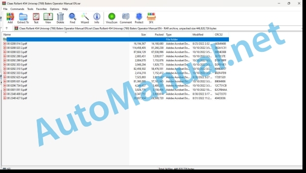
File List:
00 0288 014 3.pdf
00 0288 023 2.pdf
00 0288 023 3.pdf
00 0292 288 0.pdf
00 0292 299 0.pdf
00 0292 303 0.pdf
00 0292 310 5.pdf
00 0292 333 0.pdf
00 0292 625 4.pdf
00 0295 631 4.pdf
00 0296 734 0.pdf
00 0301 051 0.pdf
00 2348 408 0.pdf
00 2348 427 0.pdf
00 0288 014 3.pdf:
EASY on board app
Table of contents
1 Introduction
1.1 General information
1.1.1 Validity of the manual
1.1.2 Information about this Operator’s Manual
1.1.3 Symbols and notes
1.1.4 Qualified specialist workshop
1.1.5 Maintenance notes
1.1.6 Notes on warranty
1.1.7 Spare parts and technical questions
1.1.8 Technical requirements
1.2 Intended use
1.2.1 Intended use
1.2.2 Reasonably foreseeable misuse
2 Safety
2.1 Identifying warnings
2.1.1 Hazard signs
2.1.2 Signal word
2.2 Safety rules
2.2.1 Meaning of Operator’s Manual
2.2.2 Requirements made on all persons working with the product
2.2.3 Hazard areas
2.2.4 Check interactions with self-propelled machines / tractors and implements
2.2.5 Structural changes
2.2.6 Optional equipment and spare parts
2.2.7 Technical status
2.2.8 Hazard caused by damage to the product
2.2.9 Visibility of work area
2.2.10 Glare and reflections
2.2.11 Unintentional triggering of functions
2.2.12 Hazards caused by signal tones
2.2.13 Unauthorised use
2.2.14 Use of mobile terminal outside the cab
2.2.15 Follow the safety instructions
2.2.16 Respecting technical limit values
2.2.17 Preparing the product for road travel
2.2.18 Hazards when driving on the road and on the field
2.2.19 Hazards when driving on the road with an ISOBUS implement
2.2.20 Switching off the mobile terminal while driving
2.2.21 Hazards from disturbance of WLAN environment
2.2.22 Hazards from covering up the App
2.2.23 Hazards caused by malfunctions of the app
2.2.24 Raised machine parts and loads
3 Product description
3.1 Overview and method of operation
3.1.1 Overview of CWI
3.1.2 Functions of CWI
3.2 Identification plates and identification numbers
3.2.1 CWI identification plate
3.3 Information on the product
3.3.1 Factory settings
3.3.2 Software and hardware version
3.3.3 Seal on the CWI
4 Operating and display elements
4.1 CLAAS Wireless Interface (CWI)
4.1.1 CWI operating elements
4.2 CWI Setup App
4.2.1 Overview of screen
4.2.2 Buttons
4.2.3
4.2.4
4.2.5
5 Technical specifications
5.1 CLAAS Wireless Interface (CWI)
5.1.1 Specification
6 Preparing the product
6.1 Installing the product
6.1.1 Installing the CWI Setup app
6.1.2 Installing the EASY on board app
6.1.3 Connecting the tablet
7 Operation
7.1 Initial operation
7.1.1 Establishing the WLAN connection for the first time
7.1.2 Changing factory settings
7.1.3 Establishing the WLAN connection
7.2 CWI Setup App
7.2.1 Calling up menus
7.2.2 Establishing a secure data connection
7.2.3 Deleting a secure data connection
7.2.4 Displaying the software version
7.3 CWI Setup – Settings
7.3.1 Changing settings
7.3.2 Switching LEDs on and off
7.4 CWI setup – Advanced settings
7.4.1 Deleting the connection partner in CWI
7.4.2 Deleting the connection partner on the tablet
7.4.3 Resetting the CWI to factory settings
7.4.4 Resetting the tablet to factory settings
7.4.5 Switching the CAN filter on and off
7.5 EASY on board App
7.5.1 Launching Operator’s Manual
8 Faults and remedies
8.1 Overview of problems
8.1.1 CWI faults
8.1.2 Fault message: USB charging connection was disconnected
8.1.3 Fault message: Tablet outside WLAN reception area
8.1.4 Fault message: Screen locked
9 Maintenance
9.1 Maintenance schedules
9.1.1 Daily
9.2 Tablet
9.2.1 Cleaning the tablet
9.2.2 Downloading software updates
9.2.3 Updating the operating system
10 Putting out of operation and disposal
10.1 General information
10.1.1 Decommissioning and disposal
11 EC declaration of conformity
11.1 CLAAS Wireless Interface (CWI)
11.1.1 EU Declaration of conformity
12 Technical terms and abbreviations
12.1 Terms and explanations
12.1.1 Abbreviations
12.1.2 Technical terms
00 0288 023 2.pdf:
ROLLANT 454 UNIWRAPROLLANT 455 UNIWRAP
Table of contents
1 Introduction
1.1 General information
1.1.1 Manual validity
1.1.2 Information about this Operator’s Manual
1.1.3 Symbols and notes
1.1.4 Optional equipment
1.1.5 Qualified specialist workshop
1.1.6 Maintenance notes
1.1.7 Notes on warranty
1.1.8 Spare parts and technical questions
1.2 Intended use
1.2.1 Using in line with intended usage
1.2.2 Reasonably foreseeable misuse
2 Safety
2.1 Identifying warnings
2.1.1 Hazard signs
2.1.2 Signal word
2.2 Safety rules
2.2.1 Importance of Operator’s Manual
2.2.2 Observing safety decals and warnings
2.2.3 Requirements for all persons working with the machine
2.2.4 Children in danger
2.2.5 Hazard areas
2.2.6 Presence between tractor and machine
2.2.7 Persons riding on the machine
2.2.8 Hitching the tractor to the machine
2.2.9 Danger of injury from rotating shafts
2.2.10 Structural alterations
2.2.11 Optional equipment and spare parts
2.2.12 Controlling the tractor when it is running
2.2.13 Operation only after proper putting into operation
2.2.14 Technical condition
2.2.15 Danger from damage to the machine
2.2.16 Complying with technical limit values
2.2.17 Danger from continued running of machine parts
2.2.18 Keeping safety devices functional
2.2.19 Personal protective equipment
2.2.20 Wearing suitable clothing
2.2.21 Removing dirt and loose objects
2.2.22 Preparing the machine for road travel
2.2.23 Risks when driving on the road and in the field
2.2.24 Parking the machine safely
2.2.25 Unsupervised parking
2.2.26 Unsuitable operating materials
2.2.27 Safe handling of operating and auxiliary utilities
2.2.28 Environmental protection and disposal
2.2.29 Fire prevention
2.2.30 Highly dangerous electric shock from the overhead power lines
2.2.31 Electrocution by electrical system
2.2.32 Pressurised fluids
2.2.33 Compressed air
2.2.34 Hot surfaces
2.2.35 Working on machine only after shutting it down
2.2.36 Maintenance work and repairs
2.2.37 Raised machine parts and loads
2.2.38 Risks related to welding work
2.3 Safety decals
2.3.1 Layout of safety decals
2.3.2 Location of safety stickers
3 Machine description
3.1 Existing models
3.1.1 Machine description
3.2 Overview and functions
3.2.1 Left-hand side
3.2.2 Right-hand side
3.2.3 Roller identification
3.3 Safety equipment
3.3.1 Indicator lights
3.3.2 Reflective equipment
Clearance reflectors*
3.3.3 Wheel chocks
3.3.4 Parking brake
Parking brake with lever*
Parking brake with crank handle*
Applying the parking brake
Releasing the parking brake
3.3.5 Jack stand
3.3.6 Locking the tailgate
3.3.7 Locking the film guiding rollers*
3.3.8 Locking the pick-up
3.3.9 Extinguisher
3.3.10 Emergency stop
3.3.11 Safety arm
3.4 Working and service areas
3.4.1 General points
3.4.2 Upper section of the baler
3.4.3 Rear section of the baler/wrapper
3.5 Identification plate and serial number
3.5.1 Replacement parts and technical information
3.5.2 Serial number, identification number or VIN code
3.5.3 Machine identification plate
Identification plate for a machine with European certification
Identification plate for a machine without European certification
Identification plate for countries in the Customs Union (Belarus, Kazakhstan, Russia)
3.5.4 Drawbar identification plate*
3.5.5 Axle identification plate
3.6 Information on the machine
3.6.1 Location of information stickers
3.7 General operating principle
3.7.1 General points
3.7.2 Baling cycle
3.7.3 Bale wrapping cycle
3.7.4 Complete baling-wrapping cycle for one bale
3.7.5 Coverage
3.7.6 Work modes
3.7.7 Hill mode
3.8 Control terminal
3.8.1 Control terminal
3.8.2 ISOBUS connection
3.8.3 EASY on board
3.9 Transmission and drive
3.9.1 Power transmission
3.9.2 Main drive
3.9.3 Pick-up drive
3.9.4 Rotor drive
3.9.5 Drive chains
3.10 Coupling frame
3.10.1 Types of hitch
3.11 Crop feeding
3.11.1 Pick-up
3.11.2 Crop guard
3.11.3 Short crop plate (optional)
3.11.4 Roller crop press (option)
3.12 Feeder unit
3.12.1 RotoCut cutting unit
3.12.2 Automatic deactivation of the knives at the end of baling
3.12.3 Unblocking the rotor
3.13 Baling system
3.13.1 Bale chamber and rollers
3.13.2 Baling cycle
3.13.3 MPS (Maximum Pressure System or oscillating segment) with hydraulic control
3.14 Tying system
3.14.1 Tying categories and types
3.14.2 Comfort tying
3.14.3 Tying setting
3.14.4 Net tying
3.14.5 Film tying
3.14.6 Spare net storage
3.14.7 Spare film / net storage*
3.14.8 Net box* (net tying)
3.14.9 Film / net box* (film / net tying*)
3.14.10 Tying electromagnetic brake
3.15 Bale wrapper
3.15.1 Setting the wrapping
3.15.2 Tipper
3.15.3 Wrapping table
3.15.4 Wrapping arm
3.15.5 Drawing device
3.15.6 Safety arm
3.15.7 Cutter
3.15.8 Wrapping film box
3.16 Lubricating oil system
3.16.1 Automatic chain lubrication
3.17 Greasing system
3.17.1 General points
3.17.2 Manual central lubrication (optional)
3.17.3 Automatic mechanical central lubrication (optional)
3.17.4 Electric automatic central lubrication (option)
3.18 Brake
3.18.1 General points
3.18.2 Hydraulic brakes
3.18.3 Active hydraulic brakes
3.18.4 Pneumatic brakes
3.19 Hydraulic system
3.19.1 Hydraulic blocks
3.19.2 Baler hydraulic block
3.19.3 Wrapper hydraulic block
3.19.4 Hydraulic circuit filter
3.19.5 Continuous hydraulic circulation*
3.19.6 Load-Sensing (optional)
3.20 Equipment
3.20.1 Ladder
3.20.2 Step
3.20.3 Electronic module
3.20.4 Anti-theft device*
3.20.5 Wrapping film compensator
3.20.6 82% drawing device (optional)
3.20.7 Bale twister (optional)
3.20.8 Bale discharge mat (optional)
3.20.9 Work light (optional)
3.20.10 Registration plate (depending on the country)
3.20.11 Tool box (optional)
4 Operating and display elements
4.1 COMMUNICATOR II
4.1.1 Presentation
4.1.2 Description of the COMMUNICATOR
00 0288 023 3.pdf:
Operator’s Manual
Table of contents
1 Introduction
1.1 General information
1.1.1 Manual validity
1.1.2 Information about this Operator’s Manual
1.1.3 Symbols and notes
1.1.4 Optional equipment
1.1.5 Qualified specialist workshop
1.1.6 Maintenance notes
1.1.7 Notes on warranty
1.1.8 Spare parts and technical questions
1.2 Intended use
1.2.1 Using in line with intended usage
1.2.2 Reasonably foreseeable misuse
2 Safety
2.1 Identifying warnings
2.1.1 Hazard signs
2.1.2 Signal word
2.2 Safety rules
2.2.1 Importance of Operator’s Manual
2.2.2 Observing safety decals and warnings
2.2.3 Requirements for all persons working with the machine
2.2.4 Children in danger
2.2.5 Danger zones
2.2.6 Presence between tractor and machine
2.2.7 Persons riding on the machine
2.2.8 Hitching the tractor to the machine
2.2.9 Danger of injury from rotating shafts
2.2.10 Structural alterations
2.2.11 Optional equipment and spare parts
2.2.12 Controlling the tractor when it is running
2.2.13 Operation only after proper putting into operation
2.2.14 Technical condition
2.2.15 Danger from damage to the machine
2.2.16 Complying with technical limit values
2.2.17 Danger from continued running of machine parts
2.2.18 Keeping safety devices functional
2.2.19 Personal protective equipment
2.2.20 Wearing suitable clothing
2.2.21 Removing dirt and loose objects
2.2.22 Preparing the machine for road travel
2.2.23 Risks when driving on the road and in the field
2.2.24 Parking the machine safely
2.2.25 Unsupervised parking
2.2.26 Unsuitable operating materials
2.2.27 Safe handling of operating and auxiliary utilities
2.2.28 Environmental protection and disposal
2.2.29 Fire prevention
2.2.30 Highly dangerous electric shock from the overhead power lines
2.2.31 Electrocution by electrical system
2.2.32 Pressurised fluids
2.2.33 Compressed air
2.2.34 Hot surfaces
2.2.35 Working on machine only after shutting it down
2.2.36 Maintenance work and repairs
2.2.37 Raised machine parts and loads
2.2.38 Risks related to welding work
2.3 Safety decals
2.3.1 Structure of safety decals
2.3.2 Location of safety stickers
3 Machine description
3.1 Existing models
3.1.1 Machine description
3.2 Overview and functions
3.2.1 Left-hand side
3.2.2 Right-hand side
3.2.3 Roller identification
3.3 Safety equipment
3.3.1 Indicator lights
3.3.2 Reflective equipment
Clearance reflectors*
3.3.3 Wheel chocks
3.3.4 Parking brake
Parking brake with lever*
Parking brake with crank handle*
Applying the parking brake
Releasing the parking brake
3.3.5 Jack stand
3.3.6 Locking the tailgate
3.3.7 Locking the film guiding rollers*
3.3.8 Locking the pick-up
3.3.9 Extinguisher
3.3.10 Emergency stop
3.3.11 Safety arm
3.4 Working and service areas
3.4.1 General points
3.4.2 Upper section of the baler
3.4.3 Rear section of the baler/wrapper
3.5 Identification plate and serial number
3.5.1 Replacement parts and technical information
3.5.2 Serial number, identification number or VIN code
3.5.3 Machine identification plate
Identification plate for a machine with European certification
Identification plate for a machine without European certification
Identification plate for countries in the Customs Union (Belarus, Kazakhstan, Russia)
3.5.4 Drawbar identification plate*
3.5.5 Axle identification plate
3.6 Information on the machine
3.6.1 Location of information stickers
3.7 General operating principle
3.7.1 General points
3.7.2 Baling cycle
3.7.3 Bale wrapping cycle
3.7.4 Complete baling-wrapping cycle for one bale
3.7.5 Coverage
3.7.6 Work modes
3.7.7 Hill mode
3.8 Control terminal
3.8.1 Control terminal
3.8.2 COMMUNICATOR*
3.8.3 ISOBUS connection
3.9 Transmission and drive
3.9.1 Power transmission
3.9.2 Main drive
3.9.3 Pick-up drive
3.9.4 Rotor drive
3.9.5 Drive chains
3.10 Coupling frame
3.10.1 Types of hitch
3.11 Crop feeding
3.11.1 Pick-up
3.11.2 Crop guard
3.11.3 Short crop plate (optional)
3.11.4 Roller crop press (option)
3.12 Feeder unit
3.12.1 ROTO CUT cutting unit
3.12.2 Automatic deactivation of the knives at the end of baling
3.12.3 Unblocking the rotor
3.13 Baling system
3.13.1 Bale chamber and rollers
3.13.2 Baling cycle
3.13.3 MPS (Maximum Pressure System or oscillating segment) with hydraulic control
3.14 Tying system
3.14.1 Tying categories and types
3.14.2 Comfort tying
3.14.3 Tying setting
3.14.4 Net tying
3.14.5 Film tying
3.14.6 Spare net storage
3.14.7 Spare film / net storage*
3.14.8 Net box* (net tying)
3.14.9 Film / net box* (film / net tying*)
3.14.10 Tying electromagnetic brake
3.15 Bale wrapper
3.15.1 Adjusting the wrapping
3.15.2 Tipper
3.15.3 Wrapping table
3.15.4 Wrapping arm
3.15.5 Pre-stretcher
3.15.6 Safety arm
3.15.7 Cutter
3.15.8 Wrapping film box
3.16 Lubricating oil system
3.16.1 Automatic chain lubrication
3.17 Greasing system
3.17.1 General points
3.17.2 Manual central lubrication (optional)
3.17.3 Automatic mechanical central lubrication (optional)
3.17.4 Electric automatic central lubrication (option)
3.18 Brake
3.18.1 General points
3.18.2 Hydraulic brakes
3.18.3 Active hydraulic brakes
3.18.4 Pneumatic brakes
3.19 Hydraulic system
3.19.1 Hydraulic blocks
3.19.2 Baler hydraulic block
3.19.3 Wrapper hydraulic block
3.19.4 Hydraulic circuit filter
3.19.5 Continuous hydraulic circulation*
3.19.6 Load-Sensing (optional)
3.20 Equipment
3.20.1 Ladder
3.20.2 Step
3.20.3 Electronic module
3.20.4 Anti-theft device*
3.20.5 Wrapping film compensator
3.20.6 82% drawing device (optional)
3.20.7 Bale twister (optional)
3.20.8 Bale discharge mat (optional)
3.20.9 Work light* and camera*
3.20.10 Registration plate (depending on the country)
3.20.11 Tool box (optional)
4 Operating and display elements
4.1 CEMIS 700
4.1.1 Presentation
4.1.2 Description of the
4.1.3 Description of the
4.1.4 Description of the
4.1.5 Description of the
4.1.6 Description of the
4.2 COMMUNICATOR II
4.2.1 Presentation
4.3 ISOBUS terminal
4.3.1 Presentation
4.3.2 General points
4.4 CLAAS Medium Terminal
4.4.1 Presentation
4.4.2 Screen
4.4.3 Key identification
4.4.4 Home page
4.4.5 Description of the CLAAS Medium Terminal Menus
5 Technical specifications
5.1 Baler
5.1.1 Dimensions
5.1.2 Weight
5.1.3 Hitching
5.1.4 Universal drive shaft
5.1.5 Feeding and baling
5.1.6 Tying device
5.1.7 Wrapper
5.1.8 Wrapping film
5.1.9 Wheels
5.1.10 Braking
5.1.11 Hydraulic circuit
5.1.12 Greasing and lubrication
5.1.13 Bolt tightening torques
5.1.14 Noise level
5.2 Safety devices
5.2.1 Shear bolts
5.2.2 Cut-out clutch
5.2.3 Wrapper
5.3 Operating utilities
5.3.1 Lubricants
5.3.2 Tying net
5.3.3 Tying film
5.3.4 Wrapping film
5.4 Tractor
5.4.1 Power required
5.4.2 Maximum authorised weight of the towing vehicle
5.4.3 Hitching
5.4.4 Power take-off
5.4.5 Electrical connections
5.4.6 Hydraulic connections
5.4.7 Hydraulic oil and circuit
5.4.8 Braking
6 Machine preparation
6.1 Switching off and securing the machine
6.1.1 Stopping and securing the tractor and machine
6.2 Adapting the tractor
6.2.1 Checking the protective guard on the tractor PTO shaft
6.2.2 Configuring the tractor air brake system
6.2.3 Fitting the CEMIS 700*
6.2.4 Battery cable*
6.3 Adapting the machine
6.3.1 Recommendations
6.3.2 Adapting clevis hitch / swinging drawbar
6.3.3 Overlap of the universal drive shaft
6.3.4 Adapting the length of the universal drive shaft
6.4 Hitching the machine
6.4.1 Locking the hitch
6.4.2 Rubber shock absorber
6.4.3 Universal drive shaft safety advice
6.4.4 Fitting the universal drive shaft
Universal drive shaft support
Checking the turning circle
6.4.5 Machine not equipped w

%20Balers%20Operator%20Manual%20EN&url=https://pdfrepairmanual.com/docs/claas-rollant-454-uniwrap-769-balers-operator-manual-en/&media=https://pdfrepairmanual.com/wp-content/uploads/2024/04/claas-rollant-454-uniwrap-769-balers-operator-manual-en-1.jpg)


%20Component%20Technical%20Manual%20CTM205%20February%202015%20Russian&url=https://pdfrepairmanual.com/docs/john-deere-diesel-engines-4-5l-and-6-8l-component-technical-manual-ctm205-01feb15-russian/&media=https://pdfrepairmanual.com/wp-content/uploads/2023/08/john-deere-diesel-engines-45-l-and-68-l-primary-engine-component-technical-manual-ctm205-february-2015-russian-1.jpg)


%20Component%20Technical%20Manual%20CTM147%2005JUN98&url=https://pdfrepairmanual.com/docs/john-deere-df-series-150-and-250-transmissions-analog-component-technical-manual-ctm147-05jun98/&media=https://pdfrepairmanual.com/wp-content/uploads/2023/08/john-deere-df-series-150-and-250-transmissions-analog-component-technical-manual-ctm147-05jun98-1.jpg)
There are no reviews yet.