

Description
-
Model List:
- Perkins 700 Series
- 1. USERS HANDBOOK
- 1.1. General information
- 1.1.1. Title page
- 1.1.2. Introduction
- 1.1.3. Contents
- 1.1.4. How to care for your engine
- 1.1.5. Safety precautions
- 1.1.6. Engine identification
- 1.1.7. Perkins companies
- 1.2. Engine Views
- 1.2.1. Introduction
- 1.2.2. Location of engine parts
- 1.3. Operation Instructions
- 1.3.1. How to start a cold engine in cold conditions
- 1.3.2. How to start a cold engine in temperate conditions
- 1.3.3. How to stop the engine
- 1.3.4. Adjustment of engine speed range
- 1.3.5. Runningin
- 1.3.6. How to start the engine
- 1.3.7. Engine operation at idle speed
- 1.3.8. Altitude
- 1.3.9. Angle of tilt
- 1.4. Preventive Maintenance
- 1.4.1. Preventive maintenance periods
- 1.4.2. Schedules
- 1.4.3. How to drain the cooling system
- 1.4.4. How to check the specific gravity of the coolant
- 1.4.5. How to check the drive belt
- 1.4.6. How to adjust the belt tension
- 1.4.7. How to renew the element / canister of the fuel filter
- 1.4.8. Atomiser fault
- 1.4.9. How to renew an atomiser UA and UC engines
- 1.4.10. How to renew an atomiser UB engines
- 1.4.11. How to eliminate air from the fuel system
- 1.4.12. How to renew the lubricating oil
- 1.4.13. How to renew the canister of the lubricating oil filter
- 1.4.14. How to renew the engine breather assembly UA and UB engines
- 1.4.15. Air filter
- 1.4.16. How to set the valve tip clearances
- 1.5. Engine Fluids
- 1.5.1. Fuel specification
- 1.5.2. Lubricating oil specification
- 1.5.3. Coolant specification
- 1.6. Fault Diagnosis
- 1.6.1. Problems and possible causes
- 1.6.2. List of possible causes
- 1.7. Engine Preservation
- 1.7.1. Introduction
- 1.7.2. Procedure
- 1.8. Parts and Service
- 1.8.1. Introduction
- 1.8.2. Service literature
- 1.8.3. Training
- 1.8.4. POWERPART recommended consumable products
- 1.9. General Data
- 2. WORKSHOP MANUAL
- 2.1. How to use this manual
- 2.2. Foreword
- 2.3. Contents
- 2.4. Section 10 General Information
- 2.4.1. Consumable products.
- 2.4.2. Engine identification location
- 2.4.3. Engine views naturally aspirated engine
- 2.4.4. Engine views turbocharged engine
- 2.4.5. Compression test data
- 2.5. Section 11 Specifcations
- 2.5.1. Specifications
- 2.5.2. Recommended torque tensions
- 2.5.3. Data and dimensions
- 2.6. Section 12 Cylinder Head Assembly
- 2.6.1. Rocker cover to remove and to fit
- 2.6.2. Rocker assembly (latest engine) to remove and to fit
- 2.6.3. Rocker assembly (earlier engines) to remove and to fit
- 2.6.4. Rocker shaft (latest engines) to dismantle, to inspect and to assemble
- 2.6.5. Rocker shaft (earlier engines) to dismantle, to inspect and to assemble
- 2.6.6. Valve tip clearance to check
- 2.6.7. Valve springs (with cylinder head fitted) to remove and to fit
- 2.6.8. Exhaust / Induction manifolds and gaskets to remove and to fit
- 2.6.9. Cylinder head setscrews to remove and to fit
- 2.6.10. Cylinder head gasket to remove and to fit
- 2.6.11. Valve and valve springs to remove and to fit
- 2.6.12. Valve stem to inspect
- 2.6.13. Valve depth to check
- 2.6.14. Valve guides to check
- 2.6.15. Valve guides to remove and to fit
- 2.6.16. Valve seats to correct
- 2.6.17. Valve seat insert to fit
- 2.6.18. Cylinder head to check the distortion of the lower face
- 2.7. Section 13 Connecting Rod Assembly
- 2.7.1. Big end bearing and cap to remove and to fit
- 2.7.2. Piston and connecting rod to dismantle and assemble
- 2.7.3. Piston and piston ring inspection
- 2.7.4. Piston and piston ring to inspect
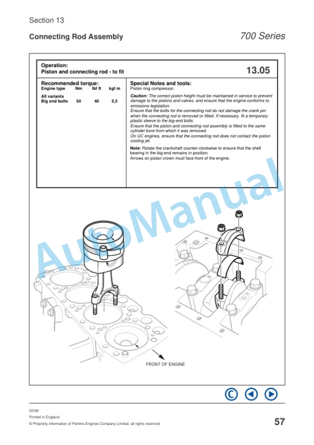
- 2.7.5. Piston and connecting rod to fit
- 2.7.6. Connecting rod to check for bend and to inspect
- 2.7.7. Connecting rod to check the length and to inspect
- 2.7.8. Small end bush to remove and to fit
- 2.7.9. To check the piston height above the cylinder block
- 2.7.10. Piston cooling jets (UC engines) to remove and to fit and to align
- 2.8. Section 14 Crankshaft Assembly
- 2.8.1. Crankshaft pulley to remove and to fit
- 2.8.2. Crankshaft pulley to fit a wear sleeve
- 2.8.3. Rear oil seal to remove
- 2.8.4. Rear oil seal to fit
- 2.8.5. Thrust washers and crankshaft endfloat to inspect
- 2.8.6. Thrust washers to remove and to fit
- 2.8.7. Main bearing caps (with crankshaft in position) to remove and to fit
- 2.8.8. Main bearings to inspect
- 2.8.9. Main bearing caps (front and rear) to remove
- 2.8.10. Main bearing caps (front and rear) to fit
- 2.8.11. Crankshaft to remove
- 2.8.12. Crankshaft to fit
- 2.8.13. Crankshaft to inspect and to overhaul
- 2.8.14. Wearsleeve to fit
- 2.9. Section 15 Timing Case and Drive Assembly
- 2.9.1. Tamper proof screws
- 2.9.2. Timing case to remove and to fit
- 2.9.3. Timing case to fit
- 2.9.4. Timing case to renew
- 2.9.5. Front oil seal to remove and to fit
- 2.9.6. Idler gear to remove
- 2.9.7. Idler gear bushes to remove and to fit
- 2.9.8. Idler gear hub to remove and to fit
- 2.9.9. Camshaft assembly for the fuel injection pump to remove and to fit
- 2.9.10. Camshaft assembly and tappets for the valves to remove and to fit
- 2.9.11. Camshaft assembly for the valves to remove and to fit
- 2.9.12. Crankshaft gear to remove and to fit
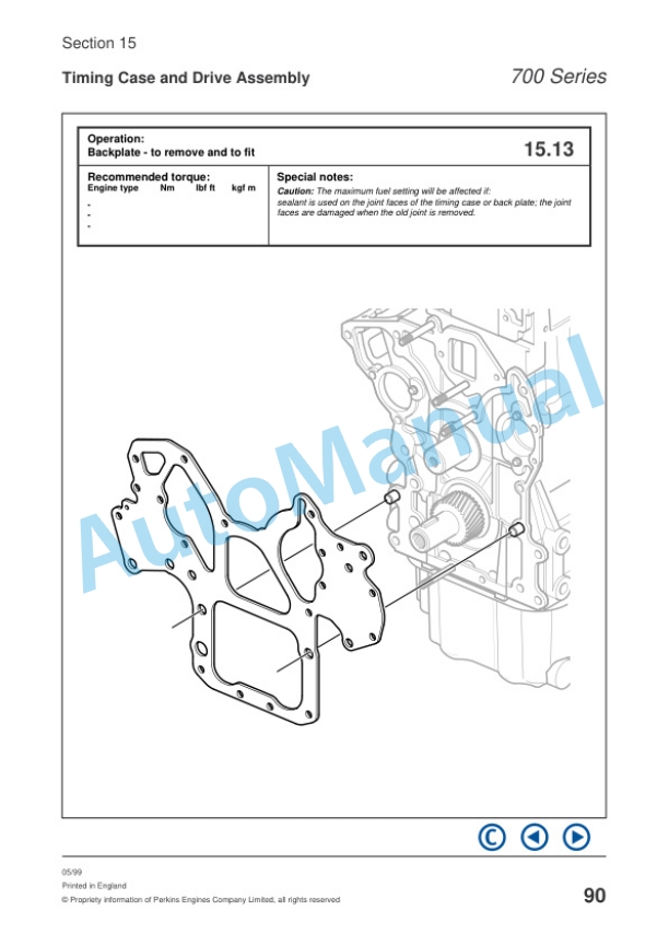
- 2.9.13. Backplate to remove and to fit
- 2.10. Section 16 Cylinder Block Assembly
- 2.10.1. Cylinder block bores to inspect
- 2.10.2. Camshaft bush to renew
- 2.11. Section 17 Engine Timing
- 2.11.1. To set accurately number 1 piston to TDC on the compression stroke
- 2.11.2. To set accurately number 1 piston to TDC on the compression stroke
- 2.11.3. To check valve timing
- 2.11.4. Fuel injection pump timing
- 2.12. Section 18 Turbo charger
- 2.12.1. Turbocharger to remove and to fit
- 2.12.2. To clean the impeller and compressor casing
- 2.12.3. Engine breather assembly to renew
- 2.13. Section 19 Lubrication System
- 2.13.1. Oil filter canister to renew
- 2.13.2. Engine lubricating oil to renew
- 2.13.3. Filter head and oil cooler to remove and fit
- 2.13.4. Sump to remove and to fit
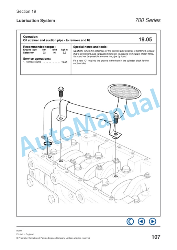
- 2.13.5. Oil strainer and suction pipe to remove and fit
- 2.13.6. Lubricating oil pump to renew
- 2.13.7. Lubrication oil pump to inspect
- 2.13.8. Relief valve to remove, to fit and to renew
- 2.14. Section 20 Fuel System
- 2.14.1. Fuel filter element to renew
- 2.14.2. Atomiser fault to inspect
- 2.14.3. High pressure fuel pipes to remove and to fit
- 2.14.4. Leak off rail to remove and to fit
- 2.14.5. Atomisers to remove and to fit
- 2.14.6. Fuel lift pump to remove and to fit
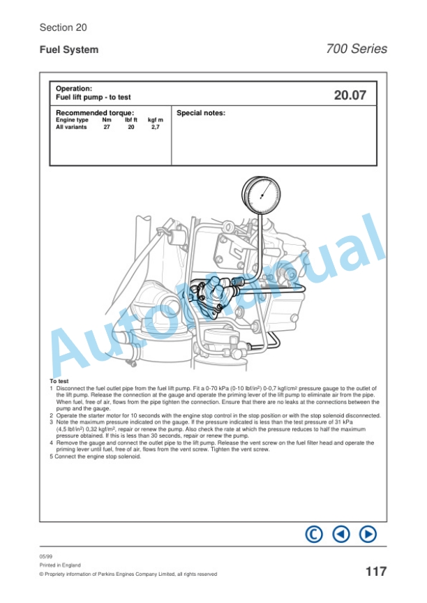
- 2.14.7. Fuel lift pump to test
- 2.14.8. Fuel injection pump to remove and to fit
- 2.14.9. To eliminate air from fuel system
- 2.14.10. Governor weight assembly to remove and to fit
- 2.14.11. Speed control lever assembly to remove and to fit
- 2.14.12. Speed control lever assembly to renew
- 2.14.13. To change a plain bush to a threaded bush
- 2.14.14. Fuel injection pump linkage to remove and to fit
- 2.14.15. Fuel injection pump linkage to renew
- 2.14.16. To record the maximum fuel position of the fuel control rack
- 2.14.17. How to use the reference setting for maximum fuel
- 2.15. Section 21 Cooling System
- 2.15.1. To drain and to fill
- 2.15.2. Thermostat to remove and to fit
- 2.15.3. Thermostat to test
- 2.15.4. Fan to remove and to fit
- 2.15.5. Coolant pump to remove and to fit
- 2.15.6. Oil cooler to remove and to fit
- 2.16. Section 22 Flywheel System
- 2.16.1. Flywheel to remove and to fit
- 2.16.2. Flywheel to inspect
- 2.16.3. Starter ring to remove and to fit
- 2.16.4. Flywheel housing to remove and to fit
- 2.17. Section 23 Electrical Equipment
- 2.17.1. Drive belt to remove and to fit
- 2.17.2. Alternator to remove and to fit
- 2.17.3. Glowplugs (starting aid) to remove and to fit
- 2.17.4. Glowplugs (starting aid) to check
- 2.17.5. Starter motor to remove, to fit and to test
- 2.17.6. Electrical stop solenoid to remove and to fit
- 2.18. Section 24 Auxiliary Equipment
- 2.18.1. Power takeoff assembly to remove and to fit
- 2.18.2. Power takeoff assembly to dismantle and to assemble
- 2.19. Section 25 Special Equipment
- 2.19.1. List of special tools
There are no reviews yet.