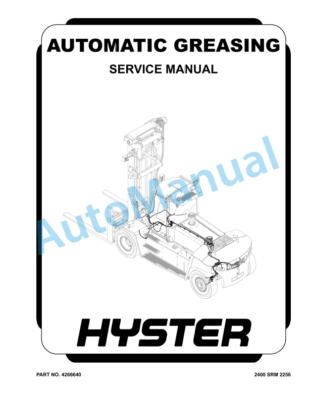
Hyster Automatic Greasing Service Manual
$30.00
- Type Of Manual: Service Manual
- Number of Pages: 210
- Size: 20.0MB
- Format: PDF
Description
- 1. RM2256-(01-2020)-US-EN
- 1.1. Series Code / Model Designation Reference Table
- 1.2. General
- 1.3. Greasing System
- 1.3.1. Grease Pump Assembly
- 1.3.1.1. Install
- 1.4. Greasing System Components
- 1.4.1. Grease Line Identification
- 1.4.2. Grease Reservoir
- 1.4.2.1. Disassemble
- 1.4.2.2. Assemble
- 1.4.3. Refilling the Grease Reservoir
- 1.4.4. Test Cycles Using the Button on the Pump
- 1.4.5. Bleeding the Pump
- 1.4.6. Bleeding the System
- 1.5. Checks and Adjustments
- 1.5.1. Test Procedures
- 1.5.1.1. Check pressure switch (valve) and cable.
- 1.5.1.2. Check pump and 5/2-way valve.
- 1.5.1.3. Check for Internal System Leaks
- 1.6. Technical Data
- 1.6.1. Pump Unit
- 1.6.2. Grease Recommendations
- 1.6.3. Electrical
- 1.7. Torque Specifications
- 2. RM2258-(01-2020)-US-EN
- 2.1. Series Code / Model Designation Reference Table
- 2.2. Counterweight Weights
- 2.3. Lift Truck Weights
- 2.4. Capacities
- 2.5. Electrical System
- 2.6. Engine Specifications
- 2.7. Mast Speeds
- 2.8. Tire Sizes
- 2.9. Hydraulic System
- 2.10. Torque Specifications, General
- 2.10.1. Transmission ZF
- 2.10.2. Counterweight
- 2.10.3. Steering
- 2.10.4. Wheel Nuts
- 2.10.5. Hydraulic System
- 2.10.6. Carriage
- 2.10.7. Tilt Cylinders
- 2.11. Torque Specifications, Cummins Diesel
- 2.11.1. Lubrication System
- 3. RM2259-(01-2020)-US-EN
- 3.1. Series Code / Model Designation Reference Table
- 3.2. Electrical Schematic T3/T4 Final
- 3.3. Hydraulic Schematic
- 4. RM2260-(01-2020)-US-EN
- 4.1. Series Code / Model Designation Reference Table
- 4.2. General
- 4.2.1. Precautions
- 4.3. Main Components
- 4.3.1. Hood Assembly
- 4.3.1.1. Install
- 4.3.2. Running Boards, Steps and Mud Flaps
- 4.3.3. Counterweight
- 4.3.3.1. Install
- 4.3.4. Label Replacement
- 5. RM2262-(01-2020)-US-EN
- 5.1. Series Code / Model Designation Reference Table
- 5.2. General
- 5.2.1. Serial Number Data
- 5.3. Truck Handling Procedures
- 5.3.1. Moving and Towing a Lift Truck
- 5.3.1.1. Precautions
- 5.3.1.2. Towing the Truck
- 5.3.2. Putting a Lift Truck on Blocks
- 5.3.2.1. Raising the Drive Tires
- 5.3.2.2. Raising the Steering Tires
- 5.3.3. Cleaning a Lift Truck
- 5.4. Safety Procedures Before Starting Maintenance
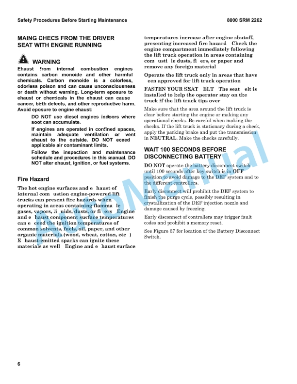
- 5.4.1. Making Checks From the Driver Seat with Engine Running
- 5.4.1.1. Fire Hazard
- 5.4.2. Wait 100 Seconds Before Disconnecting Battery
- 5.5. Periodic Maintenance Schedule
- 5.5.1. Daily Inspection
- 5.5.1.1. Daily Condition Checks
- 5.5.1.2. Daily Fluid Level Checks
- 5.5.1.3. Daily Checks from the Driver Seat with Engine Running
- 5.5.2. Initial Inspection
- 5.5.2.1. First Inspection after First 20 and First 40 Hours of Operation
- 5.5.2.2. First Inspection after First 100 Hours of Operation
- 5.5.2.3. First Inspection after First 250 Hours of Operation
- 5.5.3. Periodic Maintenance
- 5.5.3.1. Inspect and Adjust
- 5.5.3.2. Annual Inspection
- 5.5.3.3. Lubricate
- 5.6. Periodic Maintenance Procedures
- 5.6.1. Air Conditioning System
- 5.6.2. Automatic Greasing System (Optional)
- 5.6.2.1. Greasing System
- 5.6.2.2. Greasing System Filter
- 5.6.3. Brake Cooling Filter
- 5.6.4. Brake System Accumulator
- 5.6.5. Cab Air Filter
- 5.6.6. Control Levers, Switches, and Pedals
- 5.6.7. Cooling System
- 5.6.7.1. Coolant Hoses
- 5.6.7.2. Coolant Level
- 5.6.7.3. Coolant Quality
- 5.6.7.4. Cooling Fan
- 5.6.8. Crankcase Breather Element (Tier 4F/Stage IV Only)
- 5.6.9. Diesel Exhaust Fluid (DEF) System
- 5.6.9.1. DEF Pump Filter
- 5.6.9.2. DEF Tank Fill Cap
- 5.6.9.3. DEF Tank Suction Filter
- 5.6.10. Drive Axle, Differential and Axle Hub Assembly
- 5.6.10.1. Check Oil level
- 5.6.10.2. Change Oil
- 5.6.10.3. Drive Wheel Hub Bearing Preload
- 5.6.11. Drive Shaft
- 5.6.12. Engine Air Filter
- 5.6.13. Engine Air Intake Piping and Charge Air Piping
- 5.6.14. Engine and Transmission Mounts
- 5.6.15. Engine Compartment
- 5.6.16. Engine Drive Belt
- 5.6.17. Engine Drive Belt Tensioner and Pulleys
- 5.6.17.1. Bearing Condition
- 5.6.17.2. Pulley Alignment
- 5.6.17.3. Tensioner Condition
- 5.6.18. Engine Oil
- 5.6.18.1. Engine Oil Level
- 5.6.18.2. Engine Oil and Engine Oil Filter
- 5.6.19. Engine Valve Adjustment
- 5.6.20. Fault Codes
- 5.6.21. Fork Guide Bearing Blocks
- 5.6.22. Fork Guide Wear Pads
- 5.6.23. Fork Pins, Carriage Pins, and Carriage Sliding Surfaces
- 5.6.24. Frame, Mast and Carriage
- 5.6.25. Fuel, Oil, DEF, or Coolant Leaks
- 5.6.26. Fuel/Water Separator and Final Fuel Filter
- 5.6.27. Fuel Tank Breather
- 5.6.28. Header Hose Assembly
- 5.6.29. Horn, Gauges, Lights, Alarms and Control System
- 5.6.30. Hydraulic System Oil
- 5.6.30.1. Hydraulic Oil Testing Procedures
- 5.6.30.2. Hydraulic Oil Replacement
- 5.6.31. Hydraulic Tank Breather
- 5.6.32. Hydraulic Tank Return Filter
- 5.6.33. Inching Pedal Sensor Calibration
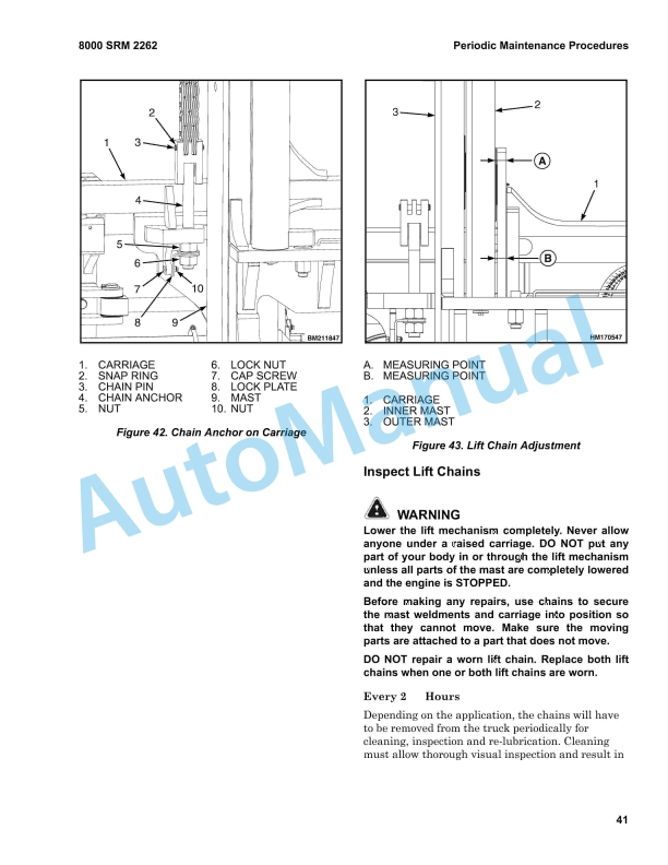
- 5.6.34. Lift Chains
- 5.6.34.1. Check and Lubricate Lift Chains
- 5.6.34.2. Adjust Lift Chains
- 5.6.34.3. Inspect Lift Chains
- 5.6.35. Lift System Accumulator (Optional)
- 5.6.36. Load Rollers
- 5.6.36.1. Carriage Load Rollers
- 5.6.36.2. (Inner) Mast Load Rollers
- 5.6.37. Mast and Carriage
- 5.6.38. Mast Pivot Pins
- 5.6.39. Operator Presence System
- 5.6.40. Operator Restraint System
- 5.6.40.1. Seat Belt and Seat Rails
- 5.6.40.2. Steering Column Pedal
- 5.6.41. Parking and Service Brakes
- 5.6.42. Radiator Assembly
- 5.6.43. Steering Axle Grease Fittings
- 5.6.43.1. King Pins
- 5.6.43.2. Tie Rod Pins
- 5.6.43.3. Pivot Pin
- 5.6.44. Steering System
- 5.6.45. Steering Wheel Hub Bearings
- 5.6.45.1. Remove and Disassemble
- 5.6.45.2. Clean and Inspect
- 5.6.45.3. Assemble and Install
- 5.6.46. Tilt Cylinder Pivot Pins
- 5.6.47. Transmission
- 5.6.47.1. Transmission Clutch Calibration
- 5.6.47.2. Transmission Oil Level
- 5.6.47.3. Transmission Oil and Oil Filter
- 5.6.48. Turbo Charger
- 5.6.49. Vibration Damper (Viscous)
- 5.6.50. Warning and Safety Labels
- 5.6.51. Windows and Mirrors
- 5.6.52. Windshield Washer Fluid Level
- 5.6.53. Wheels and Tires
- 5.6.53.1. Wheels, Tires, and Tire Pressure
- 5.6.53.2. Remove Wheels from Lift Truck
- 5.6.53.3. Adding Air Pressure to Pneumatic Tires
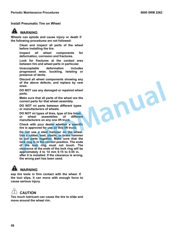
- 5.6.53.4. Install Wheels on Lift Truck
- 5.7. Capacities and Specifications
- 5.7.1. Approved Fuel and Engine Oils
- 5.7.2. Approved Oils, Fluids, and Grease
- 5.7.3. Engine Oil Viscosity
- 5.7.4. Lift Chain Lubricant Requirements
- 5.7.5. Electrical Components
- 5.7.5.1. Cab Electric Group
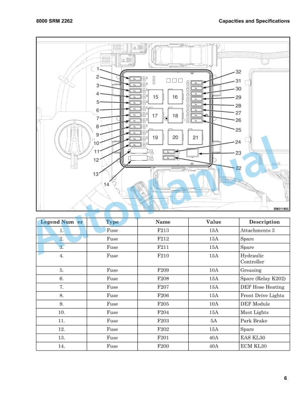
- 5.7.5.2. Check the Fuses
- 5.7.5.3. Power Distribution Group
- 6. RM2263-(12-2019)-US-EN
- 6.1. Series Code / Model Designation Reference Table
- 6.2. General
- 6.3. Weight and Dimensions
- 6.4. Loading Procedures
- 6.4.1. Loading A Truck on a Transport
- 6.4.2. Loading Disassembled Components
- 6.5. Unloading Procedures
- 6.5.1. Unloading A Truck From Transport
- 6.5.1.1. Lifting a Truck
- 6.5.1.2. Driving a Truck Off a Trailer
- 6.5.2. Unloading Disassembled Components
- 6.6. Moving and Towing
- 6.6.1. Moving a Disabled Lift Truck
- 6.6.1.1. Precautions
- 6.6.2. Towing A Lift Truck
- 6.7. Safety Procedures When Working Near The Mast
- 6.7.1. When Working Near The Mast Always
- 6.7.2. Before Starting Repairs To The Hydraulic System Always
- 6.8. Truck Assembly
- 6.8.1. Mast Installation
- 6.8.1.1. Preparations
- 6.8.1.2. Installing the Mast
- 6.8.1.3. Installing the Tilt Cylinders
- 6.8.1.4. Adjusting the Tilt Cylinders
- 6.8.1.5. Connecting the Lift Cylinders
- 6.8.1.6. Connecting the Mast Supply Hoses
- 6.8.2. Carriage and Forks
- 6.8.2.1. Installing the Carriage
- 6.8.2.2. Connecting the Header Hoses to the Carriage
- 6.8.2.3. Install the Forks
- 6.8.2.4. Adjusting the Carriage
- 6.8.2.5. Adjusting Header Hose Tension
- 6.8.2.6. Adjusting the Electrical Cable Tension
- 6.8.3. Installing the Cab Lights
- 6.8.4. Lubrication Points
- 6.9. General Checks After Assembly
- 6.9.1. Plumbing Check
- 6.9.2. Lubrication Check
- 6.9.3. Fluid Level Check
- 6.9.4. Functionality Check
- 6.9.5. Literature Package Check
- 6.9.6. Cleaning
- 6.10. Wheels and Tires
- 6.10.1. Remove Wheels From Lift Truck
- 6.10.2. Adding Air Pressure to Tires
- 6.10.3. Install Wheels on Lift Truck
- 6.11. Capacities and Specifications
- 6.11.1. Torque Values
- 6.12. Pre-Delivery
- 6.12.1. Perform Pre-Delivery Inspection
- 6.13. Delivery
- 6.13.1. Instructions Operating Manual
- 6.13.2. Instructions Daily Maintenance
- 6.13.3. Handing Over Truck


%20Service%20Manual&url=https://pdfrepairmanual.com/docs/hyster-c004-s3-00-5-50e-service-manual/&media=https://pdfrepairmanual.com/wp-content/uploads/2026/01/hyster-c004-s300-550e-service-manual-1.jpg)

%20Service%20Manual&url=https://pdfrepairmanual.com/docs/hyster-a406-r1-4-r1-6-service-manual/&media=https://pdfrepairmanual.com/wp-content/uploads/2026/01/hyster-a406-r14-r16-service-manual-1.jpg)


%20Service%20Manual&url=https://pdfrepairmanual.com/docs/hyster-c005-h60-90c-service-manual/&media=https://pdfrepairmanual.com/wp-content/uploads/2026/01/hyster-c005-h60-90c-service-manual-1.jpg)
%20Service%20Manual&url=https://pdfrepairmanual.com/docs/hyster-c010-s1-50-2-00xms-service-manual/&media=https://pdfrepairmanual.com/wp-content/uploads/2026/01/hyster-c010-s150-200xms-service-manual-1.jpg)
%20Service%20Manual&url=https://pdfrepairmanual.com/docs/hyster-c001-h25-35xl-service-manual/&media=https://pdfrepairmanual.com/wp-content/uploads/2026/01/hyster-c001-h25-35xl-service-manual-1.jpg)
%20Service%20Manual&url=https://pdfrepairmanual.com/docs/hyster-b447-s1-0c-s1-2c-s1-5c-service-manual/&media=https://pdfrepairmanual.com/wp-content/uploads/2026/01/hyster-b447-s10c-s12c-s15c-service-manual-1.jpg)

There are no reviews yet.