
Description
-
Model List:
- 532-120, 535-125, 535-140, 537-135 (550), 540-140 (550-140), 540-170 (550-170, 5508)
- 1. Introduction
- 2. General Information ……………………………………………………………………………1
- 3. Machine Model and Serial Number ………………………………………………….1
- 4. About this Supplement …………………………………………………………………..1
- 5. Safety Check List ……………………………………………………………………………….2
- 6. System Overview ……………………………………………………………………………….4
- 7. Introduction …………………………………………………………………………………..4
- 8. Controls ……………………………………………………………………………………….4
- 9. Remote Servo Control ……………………………………………………………………4
- 10. Emergency Operation ……………………………………………………………………4
- 11. Motion Cut Out (MC) (if fitted) …………………………………………………………4
- 12. Component Location and Identification …………………………………………….5
- 13. System Operation ………………………………………………………………………….7
- 14. Service Procedures
- 15. RCU Engine Start Procedure ……………………………………………………………….9
- 16. Fault Finding ……………………………………………………………………………………10
- 17. Introduction …………………………………………………………………………………10
- 18. Tables ……………………………………………………………………………………….. 11
- 19. Servicemaster Tools …………………………………………………………………………13
- 20. Manplatform Diagnostics – User Guide ………………………………………………..14
- 21. Introduction …………………………………………………………………………………14
- 22. Care and Safety ………………………………………………………………………….14
- 23. Installing Manplatform Diagnostics …………………………………………………14
- 24. Connecting Manplatform Diagnostics ……………………………………………..15
- 25. Starting the Manplatform Diagnostics Software ………………………………..18
- 26. Remote Control Unit Test ……………………………………………………………..19
- 27. Internal Monitor …………………………………………………………………………..20
- 28. Error log ……………………………………………………………………………………..21
- 29. 540 Valve (540-170 machine only) …………………………………………………21
- 30. Cabin Joystick …………………………………………………………………………….21
- 31. Remote Control …………………………………………………………………………..21
- 32. Stabilizer Joystick (3 Stage Only) …………………………………………………..22
- 33. Connector I-O ……………………………………………………………………………..23
- 34. Manplatform Calibration – User Guide …………………………………………………30
- 35. Introduction …………………………………………………………………………………30
- 36. Care and Safety ………………………………………………………………………….30
- 37. Installing Manplatform Calibration ………………………………………………….30
- 38. Connecting Manplatform Calibration ………………………………………………31
- 39. Starting the Manplatform Calibration Software …………………………………34
- 40. Introduction …………………………………………………………………………………35
- 41. Manplatform Enable – Machines With Motion Cut Out (MCO) ……………36
- 42. Machine Model Setup …………………………………………………………………..37
- 43. Load Signal ………………………………………………………………………………..40
- 44. Stabilizer Joystick Setup (3-Stage Boom Machines) …………………………42
- 45. Travel Speeds (Part 1) ………………………………………………………………….43
- 46. Travel Speeds (Part 2) ………………………………………………………………….46
- 47. Hydraulic Control Sensitivity ………………………………………………………….49
- 48. Electrics
- 49. Fuses and Relays …………………………………………………………………………….52
- 50. Quick Reference ………………………………………………………………………….53
- 51. Schematic Circuits ……………………………………………………………………………70
- 52. Machines with R-Series Engines ……………………………………………………70
- 53. Machines with JCB Dieselmax Engines ………………………………………….76
- 54. Engine Start Operation – Cabin Mode ………………………………………………….77
- 55. Engine Start Operation – Remote Mode ………………………………………………78
- 56. Stabilizer Legs Down ……………………………………………………………………79
- 57. Park Brake ON ……………………………………………………………………………80
- 58. Emergency Isolation Switch ………………………………………………………….81
- 59. Receiver Signal Integrity ………………………………………………………………82
- 60. Remote Mode Select ……………………………………………………………………83
- 61. Starter Motor Operation ………………………………………………………………..84
- 62. Machine Operation – Remote Mode ……………………………………………………85
- 63. Receiver Signal Integrity ………………………………………………………………86
- 64. Stabilizer and Sway Isolation …………………………………………………………87
- 65. Boom Angle Limit (4 Stage Boom) …………………………………………………88
- 66. Engine Speed Actuator Operation ………………………………………………….89
- 67. L.M.I. Operation ……………………………………………………………………………….90
- 68. L.M.I. Operation (3 Stage Boom) ……………………………………………………90
- 69. L.M.I. Operation (4 Stage Boom) ……………………………………………………91
- 70. Control Valve Operation ……………………………………………………………………92
- 71. Control Valve Operation (3 Stage Boom) ………………………………………..93
- 72. Control Valve Operation (4 Stage Boom) ………………………………………..94
- 73. Joystick Operation ……………………………………………………………………………95
- 74. Emergency Pump Operation ……………………………………………………………..96
- 75. Harness Drawings ……………………………………………………………………………97
- 76. Introduction …………………………………………………………………………………97
- 77. Quick Reference ………………………………………………………………………….97
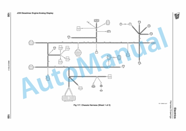
- 78. Chassis Harness …………………………………………………………………………98
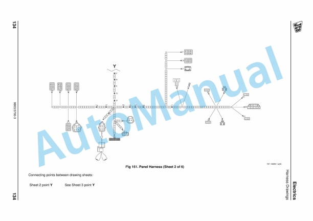
- 79. Panel Harness ………………………………………………………………………….. 110
- 80. Stabilizer Harness ……………………………………………………………………..145
- 81. Joystick …………………………………………………………………………………………149
- 82. Removal and Replacement …………………………………………………………149
- 83. LMI Transducers …………………………………………………………………………….150
- 84. Removal and Replacement …………………………………………………………150
- 85. Electronic Control Unit (LK1 ECU) ……………………………………………………151
- 86. Removal and Replacement …………………………………………………………151
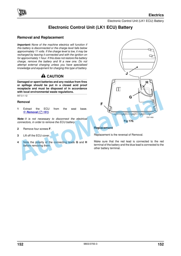
- 87. Electronic Control Unit (LK1 ECU) Battery …………………………………………152
- 88. Removal and Replacement …………………………………………………………152
- 89. Stabilizer Pressure Switches ……………………………………………………………153
- 90. Removal and Replacement …………………………………………………………153
- 91. Proximity Switches …………………………………………………………………………154
- 92. Locations ………………………………………………………………………………….154
- 93. Radio Receiver ………………………………………………………………………………156
- 94. Removal and Replacement …………………………………………………………156
- 95. Engine Speed Actuator ……………………………………………………………………158
- 96. Removal and Replacement …………………………………………………………158
- 97. Hydraulics
- 98. Technical Data ……………………………………………………………………………….160
- 99. 3-Stage Boom Machines …………………………………………………………….160
- 100. 4-Stage Boom Machines …………………………………………………………….161
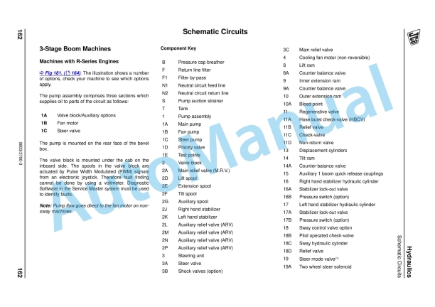
- 101. Schematic Circuits ………………………………………………………………………….162
- 102. 3-Stage Boom Machines …………………………………………………………….162
- 103. 4-Stage Boom Machines …………………………………………………………….168
- 104. Control Valve (3-Stage Boom Machines) ……………………………………………178
- 105. Operation ………………………………………………………………………………….178
- 106. Control Valve Layout ………………………………………………………………….180
- 107. Pressure Testing ………………………………………………………………………..182
- 108. Removal and Replacement …………………………………………………………186
- 109. Dismantling and Assembly ………………………………………………………….187
- 110. Control Valve (4-Stage Boom Machines) ……………………………………………195
- 111. Operation ………………………………………………………………………………….195
- 112. Removal and Replacement …………………………………………………………196
- 113. Dismantling and Assembly ………………………………………………………….197
- 114. Pilot Control Valves (4-Stage Boom Machines) …………………………………..198
- 115. Locations ………………………………………………………………………………….198
- 116. Removal and Replacement …………………………………………………………199
- 117. Needle Valve (Slewing Platforms only) ………………………………………………200
- 118. Adjustment ……………………………………………………………………………….200
- 119. Removal and Replacement …………………………………………………………200
- 120. Non-Return Valves …………………………………………………………………………201
- 121. Removal and Replacement …………………………………………………………201
- 122. Tilt Ram – Counterbalance Valves …………………………………………………….202
- 123. Removal and Replacement …………………………………………………………202
- 124. Emergency Pump …………………………………………………………………………..203
- 125. Removal and Replacement …………………………………………………………203


There are no reviews yet.