
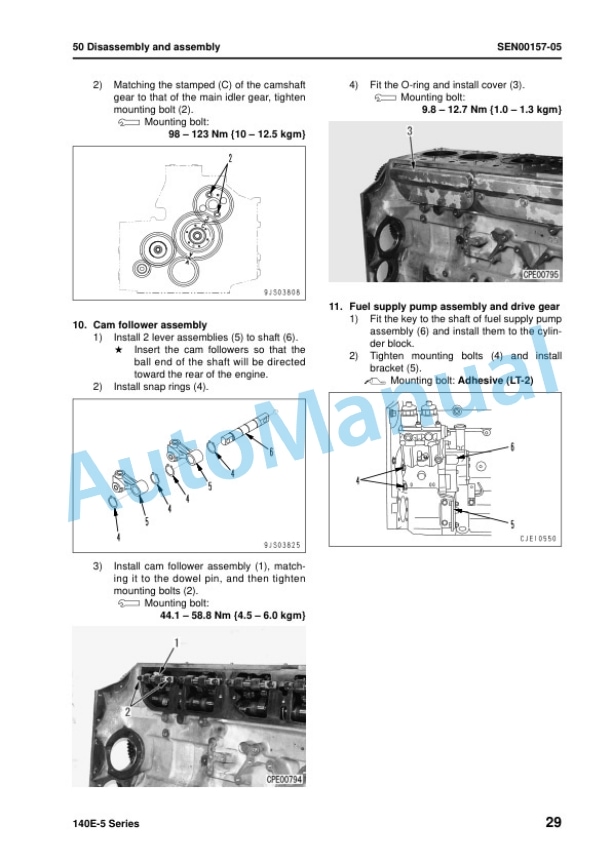
Description
-
Model List:
- 140E-5 Series Engine
- 1. COVER
- 2. Index and foreword
- 2.1. Index
- 2.1.1. Composition of shop manual
- 2.1.2. Table of contents
- 2.2. Foreword and general information
- 2.2.1. Safety notice
- 2.2.2. How to read the shop manual
- 2.2.3. Explanation of terms for maintenance standard
- 2.2.4. Handling of electric equipment and hydraulic component
- 2.2.5. Handling of connectors newly used for engines
- 2.2.6. How to read electric wire code
- 2.2.7. Precautions when carrying out operation
- 2.2.8. Method of disassembling and connecting pushpull type coupler
- 2.2.9. Standard tightening torque table
- 2.2.10. Conversion table
- 3. Specification
- 3.1. Specification and technical data
- 3.1.1. Outline
- 3.1.2. Specifications
- 3.1.3. General view
- 3.1.4. Weight table
- 3.1.5. Engine performance curves
- 4. Structure, function and maintenance standard
- 4.1. Structure, function and maintenance standard, Part 1
- 4.1.1. Air intake and exhaust unit
- 4.1.2. Main moving parts
- 4.1.3. Crankshaft
- 4.1.4. Camshaft
- 4.1.5. Cam follower and push rod
- 4.1.6. Piston, piston ring and piston pin
- 4.1.7. Connecting rod
- 4.1.8. Flywheel and flywheel housing
- 4.1.9. Vibration damper
- 4.1.10. Timing gear
- 4.1.11. Valve system
- 4.1.12. Valve and valve guide
- 4.1.13. Rocker arm and shaft
- 4.1.14. Crosshead and guide
- 4.2. Structure, function and maintenance standard, Part 2
- 4.2.1. Lubrication system
- 4.2.2. Fuel system
- 4.2.3. Cooling system
- 4.2.4. Accessories
- 4.2.5. Electrical equipment
- 5. Standard value table
- 5.1. Standard service value table
- 5.1.1. Standard service value table for testing, adjusting, and troubleshooting
- 5.1.2. Runningin standard and performance test standard
- 6. Testing and adjusting
- 6.1. Testing and adjusting
- 6.1.1. Testing and adjusting (with EGR)
- 6.1.2. Testing and adjusting (EGRless)
- 7. Troubleshooting
- 7.1. General information on troubleshooting
- 7.1.1. Points to remember when troubleshooting
- 7.1.2. Method of displaying trouble diagnosis lamps (Method of displaying error code)
- 7.1.3. Error codes and failure codes list
- 7.1.4. Information in troubleshooting table
- 7.1.5. Connection table for connector pin numbers
- 7.1.6. T branch box and T branch adapter table
- 7.2. Troubleshooting of mechanical system (Smode)
- 7.2.1. Troubleshooting of mechanical system (Smode)
- 7.3. Troubleshooting of electrical system (Emode), Part 1
- 7.3.1. Troubleshooting of electrical system (Emode), Part 1
- 7.4. Troubleshooting of electrical system (Emode), Part 2
- 7.4.1. Troubleshooting of electrical system (Emode), Part 2
- 8. Disassembly and assembly
- 8.1. General information on disassembly and assembly
- 8.1.1. General information on disassembly and assembly
- 8.2. Disassembly and assembly, Part 1 (with EGR)
- 8.2.1. Disassembly and assembly, Part 1 (with EGR)
- 8.3. Disassembly and assembly, Part 2 (EGRless)
- 8.3.1. Disassembly and assembly, Part 2 (EGRless)
- 8.4. Disassembly and assembly, Part 3
- 8.4.1. Disassembly and assembly, Part 3
- 9. Repair and replacement of parts
- 9.1. Information related to repair and replacement
- 9.1.1. Flowchart
- 9.1.2. Special tool table
- 9.1.3. Special tool sketch
- 9.2. Cylinder head
- 9.2.1. Part names related to cylinder head
- 9.2.2. Testing and inspection of cylinder head
- 9.2.3. Pressure test of cylinder head
- 9.2.4. Replacement of valve guide
- 9.2.5. Replacement of valve seat insert
- 9.2.6. Replacement of crosshead guide
- 9.2.7. Repair of cylinder head mounting face by grinding
- 9.2.8. Repair of valve by grinding
- 9.3. Cylinder block
- 9.3.1. Part names related to cylinder block
- 9.3.2. Testing and inspection of cylinder block
- 9.3.3. Method of checking main bearing metal inside diameter with alignment bar
- 9.3.4. Part names related to crankshaft
- 9.3.5. Testing and inspection of crankshaft
- 9.3.6. Part names related to connecting rod
- 9.3.7. Testing and inspection of connecting rod
- 9.3.8. Replacement of flywheel ring gear
- 9.3.9. Replacement of crankshaft gear
- 9.3.10. Replacement of camshaft gear
- 9.3.11. Replacement of main bearing metal cap
- 9.3.12. Replacement of connecting rod small end bushing
- 9.3.13. Replacement of cam bushing
- 9.3.14. Repair of cylinder block top by grinding
- 9.3.15. Repair of counterbore by grinding
- 9.3.16. Check and identification after repair by grinding
- 9.3.17. Gasket sealant application procedure
- 9.3.18. Repair standard for cylinder liner Oring
- 9.3.19. Replacement of engine rear seal
- 9.3.20. Replacement of wear sleeve (when sleeve is installed)
- 9.3.21. Repair of crankshaft by grinding
- 9.3.22. Improvement of surface roughness of crankshaft journal


There are no reviews yet.