
Description
-
Model List:
- 3D95E-1 Series Engine
- 1. Cover
- 2. Index and Foreword
- 2.1. Index
- 2.2. Foreword, Safety, Basic Information
- 2.2.1. How to Read the Engine Shop Manual
- 2.2.2. Safety Notice for Operation
- 2.2.3. Precautions to Prevent Fire
- 2.2.4. Procedures If Fire Occurs
- 2.2.5. Precautions When You Discard Waste Materials
- 2.2.6. Engine Technology to Conform Exhaust Gas Emission
- 2.2.7. Precautions When You Handle Hydraulic Equipment
- 2.2.8. Precautions When You Disconnect and Connect Pipings
- 2.2.9. Precautions When You Handle Electrical Equipment
- 2.2.10. Precautions When You Handle Fuel System Equipment
- 2.2.11. Precautions When You Handle Intake System Equipment
- 2.2.12. Disconnect and Connect PushPull Type Coupler
- 2.2.12.1. How to Disconnect and Connect Type 1 PushPull Type Coupler
- 2.2.12.2. How to Disconnect and Connect Type 2 PushPull Type Coupler
- 2.2.12.3. How to Disconnect and Connect Type 3 PushPull Type Coupler
- 2.2.13. Precautions for Disconnection and Connection of Connectors
- 2.2.14. Disconnect and Connect Deutsch Connector
- 2.2.15. How to Disconnect and Connect Slide Lock Type Connector
- 2.2.16. Disconnect and Connect Connector with Lock to Pull
- 2.2.17. Disconnect and Connect Connector with Lock to Push
- 2.2.18. Disconnect and Connect Connector with Housing to Rotate
- 2.2.19. Standard Tightening Torque Table
- 2.2.20. Conversion Table
- 2.2.21. Abbreviation List
- 3. Specification
- 3.1. Table of Contents
- 3.2. Specifications
- 3.2.1. Outline of Exhaust Gas Regulation
- 3.2.1.1. System Diagram of Engine Conformed to Tier4 Regulation
- 3.2.2. List of Applicable Machines 3D95E1
- 3.2.3. Specifications
- 3.2.3.1. Specifications SAA3D95E1 (PC78US11, PC78US11E0, PC78UU11, PC88MR11, PC88MR11E0)
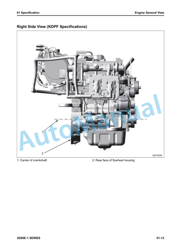
- 3.2.4. Engine General View
- 3.2.4.1. Engine General View SAA3D95E1 (PC78US11, PC78US11E0, PC78UU11, PC88MR11, PC88MR11E0)
- 3.2.5. Weight Table
- 3.2.5.1. Weight Table 3D95E1
- 3.2.6. Engine Performance Curve
- 3.2.6.1. Engine Performance Curve SAA3D95E1 (PC78US11, PC78US11E0, PC78UU11, PC88MR11, PC88MR11E0)
- 4. Structure and Function
- 4.1. Table of Contents
- 4.2. Engine System
- 4.2.1. Layout of Engine Components
- 4.2.1.1. Layout Drawing of Engine Components
- 4.2.2. Intake and Exhaust System Parts
- 4.2.2.1. Layout Drawing of Intake and Exhaust System
- 4.2.2.2. Intake and Exhaust System Circuit Diagram
- 4.2.2.3. Function of Intake and Exhaust System
- 4.2.2.4. Air Cleaner
- 4.2.2.5. Intake Air Heater
- 4.2.3. Engine Main Body Parts
- 4.2.3.1. Cylinder Head
- 4.2.3.2. Cylinder Block
- 4.2.3.3. Main Drive Parts
- 4.2.3.4. Timing Gear
- 4.2.3.5. Front Cover
- 4.2.3.6. Valve System
- 4.2.3.7. Flywheel and Flywheel Housing
- 4.2.4. Turbocharger System
- 4.2.4.1. Turbocharger
- 4.2.4.2. EGR System
- 4.2.4.3. EGR Valve
- 4.2.4.4. EGR Cooler
- 4.2.4.5. High Efficiency Breather System
- 4.2.4.6. High Efficiency Breather
- 4.2.4.7. Exhaust Throttle Valve
- 4.2.4.8. KDOC
- 4.2.4.9. KDPF
- 4.2.5. Lubrication System
- 4.2.5.1. Layout Drawing of Lubrication System Parts
- 4.2.5.2. Lubrication System Circuit Diagram
- 4.2.5.3. Engine Oil Pump
- 4.2.5.4. Engine Oil Filter
- 4.2.5.5. Engine Oil Cooler
- 4.2.5.6. Engine Oil Pan
- 4.2.6. Fuel System
- 4.2.6.1. Layout Drawing of Fuel System Parts
- 4.2.6.2. Fuel System Circuit Diagram
- 4.2.6.3. CRI System
- 4.2.6.4. Supply Pump
- 4.2.6.5. Common Rail
- 4.2.6.6. Injector
- 4.2.6.7. Fuel Prefilter
- 4.2.6.8. Fuel Main Filter
- 4.2.7. Cooling System
- 4.2.7.1. Layout Drawing of Cooling System Parts
- 4.2.7.2. Cooling System Circuit Diagram
- 4.2.7.3. Drive Pulley
- 4.2.7.4. Water Pump
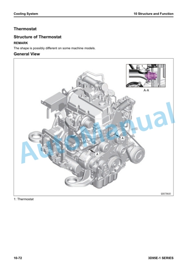
- 4.2.7.5. Thermostat
- 4.3. Electrical System
- 4.3.1. Component Parts of Electrical System
- 4.3.1.1. Alternator
- 4.3.1.2. Starting Motor
- 4.3.1.3. Engine Wiring Harness
- 4.3.1.4. Engine Controller
- 4.3.2. Sensor
- 4.3.2.1. Layout Drawing of Engine Sensor
- 4.3.2.2. Structure of Ambient Pressure Sensor
- 4.3.2.3. Function of Ambient Pressure Sensor
- 4.3.2.4. Structure of Engine Oil Pressure Switch
- 4.3.2.5. Function of Engine Oil Pressure Switch
- 4.3.2.6. Structure of Charge (Boost) Pressure and Temperature Sensor
- 4.3.2.7. Function of Charge (Boost) Pressure and Temperature Sensor
- 4.3.2.8. Structure of Coolant Temperature Sensor
- 4.3.2.9. Function of Coolant Temperature Sensor
- 4.3.2.10. Structure of NE (Crankshaft) Speed Sensor
- 4.3.2.11. Function of NE (Crankshaft) Speed Sensor
- 4.3.2.12. Structure of Bkup (Camshaft) Speed Sensor
- 4.3.2.13. Function of Bkup (Camshaft) Speed Sensor
- 4.3.2.14. Structure of Common Rail Pressure Sensor
- 4.3.2.15. Function of Common Rail Pressure Sensor
- 4.3.2.16. Structure of Mass Air Flow and Temperature Sensor
- 4.3.2.17. Function of Mass Air Flow and Temperature Sensor
- 4.3.2.18. Structure of Air Cleaner Clogging Sensor
- 4.3.2.19. Function of Air Cleaner Clogging Sensor
- 4.3.2.20. Structure of EGR Valve (with Builtin Position Sensor)
- 4.3.2.21. Function of EGR Valve (with Builtin Position Sensor)
- 4.3.2.22. Structure of Exhaust Throttle Valve (with Builtin Position Sensor)
- 4.3.2.23. Function of Exhaust Throttle Valve (with Builtin Position Sensor)
- 5. Standard Value Table
- 5.1. Table of Contents
- 5.2. Standard Value Table for Engine
- 5.2.1. Standard Value Table for Engine SAA3D95E1 (PC78US11, PC78US11E0, PC78UU11, PC88MR11, PC88MR11E0)
- 5.3. Runningin Standard and Performance Test Standard
- 5.3.1. Performance Test Standard and Standard for Operation of Engine for Break in Period SAA3D95E1 (PC78US11, PC78US11E0, PC78UU11, PC88MR11, PC88MR11E0)
- 6. Disassembly and Assembly
- 6.1. Table of Contents
- 6.2. Precautions Before Work
- 6.3. Related Information on Disassembly and Assembly
- 6.3.1. How to Read This Manual
- 6.3.2. Coating Materials List
- 6.3.3. Special Tool List
- 6.3.4. Sketches of Special Tools
- 6.4. Engine System
- 6.4.1. Disassemble and Assemble Engine Generally
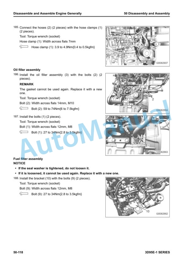
- 6.4.1.1. Disassemble Engine Generally
- 6.4.1.2. How to Assemble Engine Generally
- 6.4.2. Remove and Install Supply Pump Assembly
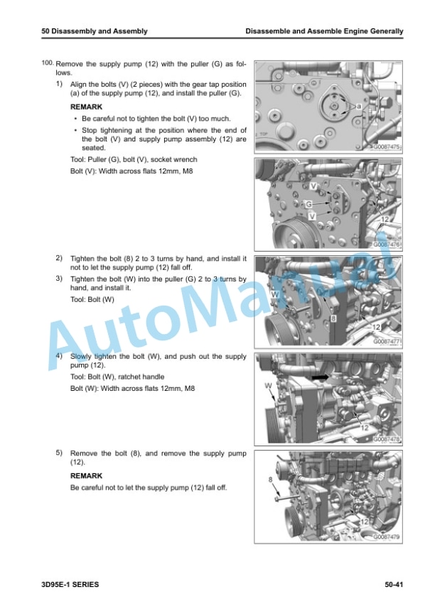
- 6.4.2.1. How to Remove Supply Pump Assembly
- 6.4.2.2. How to Install Supply Pump Assembly
- 6.4.3. Remove and Install Engine Front Oil Seal
- 6.4.3.1. How to Remove Engine Front Oil Seal
- 6.4.3.2. How to Install Engine Front Oil Seal
- 7. Maintenance Standard
- 7.1. Table of Contents
- 7.2. Explanation of Terms for Maintenance Standard
- 7.3. Engine System
- 7.3.1. Intake and Exhaust System Parts
- 7.3.1.1. Maintenance Standard for Turbocharger
- 7.3.2. Engine Main Body Parts
- 7.3.2.1. Maintenance Standard for Cylinder Head
- 7.3.2.2. Maintenance Standard for Cylinder Block
- 7.3.2.3. Maintenance Standard for Crankshaft
- 7.3.2.4. Maintenance Standard for Piston
- 7.3.2.5. Maintenance Standard for Connecting Rod
- 7.3.2.6. Maintenance Standard for Timing Gear
- 7.3.2.7. Maintenance Standard for Camshaft
- 7.3.2.8. Maintenance Standard for Valve and Valve Guide
- 7.3.2.9. Maintenance Standard for Rocker Arm
- 7.3.2.10. Maintenance Standard for Tappet
- 7.3.2.11. Maintenance Standard for Flywheel
- 7.3.3. Lubrication System
- 7.3.3.1. Maintenance Standard for Engine Oil Pump
- 8. Index


There are no reviews yet.