
Description
-
Model List:
- 6D140-2 Series Diesel Engine
- 1. Cover
- 2. Contents
- 3. General
- 3.1. Applicable machine
- 3.2. Specifications
- 3.3. General assembly drawing
- 3.4. Weight table
- 3.5. Engine performance curve
- 4. Structure and function
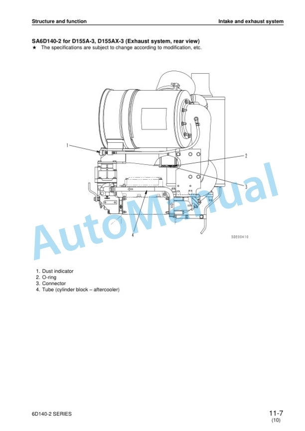
- 4.1. Intake and exhaust system
- 4.1.1. Intake and exhaust system
- 4.1.2. Main circulation system
- 4.1.3. Vibration damper
- 4.1.4. Timing gear
- 4.1.5. Valve system
- 4.1.6. Flywheel and flywheel housing
- 4.2. Lubrication system
- 4.2.1. Lubrication system chart
- 4.2.2. Oil pump
- 4.2.3. Regulator valve and piston cooling valve
- 4.2.4. Oil filter
- 4.2.5. Oil cooler
- 4.3. Fuel system
- 4.3.1. Fuel system chart
- 4.3.2. Fuel injection pump
- 4.3.3. Feed pump
- 4.3.4. Fuel injection nozzle
- 4.3.5. Fuel filter
- 4.3.6. Engine stop motor
- 4.4. Cooling system
- 4.4.1. Cooling system chart
- 4.4.2. Water pump
- 4.4.3. Thermostat
- 4.4.4. Corrosion resistor
- 4.4.5. Corrosion resistor mounting
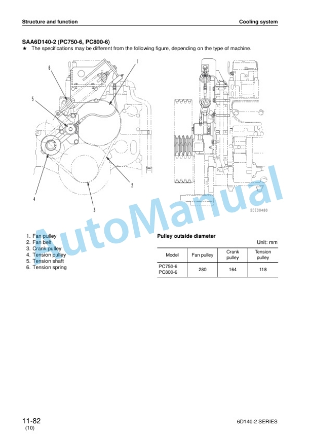
- 4.4.6. Cooling fan drive
- 4.5. Accessory
- 4.5.1. Air compressor
- 4.5.2. Exhaust brake
- 4.6. Electrical system
- 4.6.1. Alternator
- 4.6.2. Starting motor
- 4.6.3. Electrical intake air heater
- 4.6.4. Front PTO mounting
- 4.6.5. Front PTO assembly
- 4.6.6. Front PTO drive gear assembly
- 5. Testing and adjusting
- 5.1. Mounting (adjusting) methodof engine speed sensor
- 5.2. Engine body
- 5.2.1. Adjusting valve clearance
- 5.2.2. Measuring compressionpressure
- 5.3. Fuel system
- 5.3.1. Testing and adjusting fuelinjection timing
- 5.3.2. Adjusting fuel injectionpressure
- 5.3.3. Procedure for adjustingengine stop motor cable
- 5.4. Cooling system
- 5.4.1. Checking and adjusting fan belt tension
- 5.5. Fuel injection pump calibration data
- 5.6. Performance test
- 5.6.1. Runin standard
- 5.6.2. Performance test criteria
- 5.7. Troubleshooting
- 5.7.1. Points to remember when troubleshooting
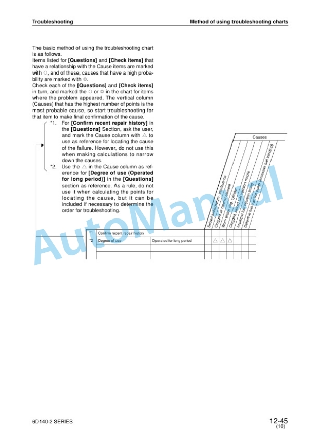
- 5.7.2. Method of using troubleshooting charts
- 5.7.3. S1 Starting performance is poor (starting always takes time)
- 5.7.4. S2 Engine does not start
- 5.7.5. S3 Engine does not pick up smoothly (followup is poor)
- 5.7.6. S4 Engine stops during operations
- 5.7.7. S5 Engine does not rotate smoothly (hunting)
- 5.7.8. S6 Engine lacks output (no power)
- 5.7.9. S7 Exhaust smoke is black (incomplete combustion)
- 5.7.10. S8 Oil consumption is excessive (or exhaust smoke is blue)
- 5.7.11. S9 Oil becomes contaminated quickly
- 5.7.12. S10 Fuel consumption is excessive
- 5.7.13. S11 Oil is in cooling water, or water spurts back, or water level goes down
- 5.7.14. S12 Oil pressure caution lamp lights up (drop in oil pressure)
- 5.7.15. S13 Oil level rises (water, fuel in oil)
- 5.7.16. S14 Water temperature becomes too high (overheating)
- 5.7.17. S15 Abnormal noise is made
- 5.7.18. S16 Vibration is excessive
- 5.7.19. Testing and adjusting tool list
- 5.7.20. Testing and adjusting dataa
- 6. DISASSEMBLY AND ASSEMBLY
- 6.1. GENERAL DISASSEMBLY
- 6.1.1. Air cleanermuffler
- 6.1.2. Starting motor
- 6.1.3. Turbocharger drain tube
- 6.1.4. Setting engine in engine overhaul stand
- 6.1.5. Corrosion resistor, air compressor suction tube
- 6.1.6. Bracket
- 6.1.7. Connector
- 6.1.8. Tension pulley assembly
- 6.1.9. Fan pulley assembly
- 6.1.10. Alternator assemblypulley
- 6.1.11. Dipstick guide, air compressor
- 6.1.12. Fuel hose
- 6.1.13. Turbocharger
- 6.1.14. Exhaust manifold
- 6.1.15. Aftercooler assembly (Intake manifold assembly)
- 6.1.16. Fuel injection tube
- 6.1.17. Fuel injection pump assembly
- 6.1.18. Tube, bracket, PTO case
- 6.1.19. Fuel filterfuel filter bracket
- 6.1.20. Oil filteroil regulator
- 6.1.21. Oil pan
- 6.1.22. Suction pipe, under frame
- 6.1.23. Flywheel
- 6.1.24. Rear seal
- 6.1.25. Flywheel housing
- 6.1.26. Air vent tube, spill pipe, rocker arm housing cover
- 6.1.27. Nozzle holder, inlet connector
- 6.1.28. Rocker arm
- 6.1.29. Push rod
- 6.1.30. Crosshead
- 6.1.31. Rocker arm housing
- 6.1.32. Cylinder head assembly
- 6.1.33. Vibration dampercrankshaft pulley assembly
- 6.1.34. Front support
- 6.1.35. Thermostat housing
- 6.1.36. Water pump assembly
- 6.1.37. Oil cooler assembly
- 6.1.38. Cam follower
- 6.1.39. Gear case cover
- 6.1.40. Injection pump drive gear
- 6.1.41. Camshaft
- 6.1.42. Oil pump assembly, oil pump idler gear
- 6.1.43. Main idler gear, injection pump drive shaft
- 6.1.44. Piston cooling nozzle
- 6.1.45. Piston and connecting rod assembly
- 6.1.46. Crankshaft
- 6.1.47. Cylinder liner
- 6.2. GENERAL ASSEMBLY
- 6.2.1. Tightening bolts by the plastic range turning angle method
- 6.2.2. Drawing of special tool
- 6.2.3. Preparatory work
- 6.2.4. Cylinder liner
- 6.2.5. Crankshaft
- 6.2.6. Piston and connecting rod assembly
- 6.2.7. Piston cooling nozzle
- 6.2.8. Main idler gear, fuel injection pump drive shaft
- 6.2.9. Oil pump idler gear, oil pump assembly
- 6.2.10. Camshaft
- 6.2.11. Fuel injection pump drive gear
- 6.2.12. Fuel injection pump drive shaft oil seal
- 6.2.13. Gear case cover
- 6.2.14. Breather
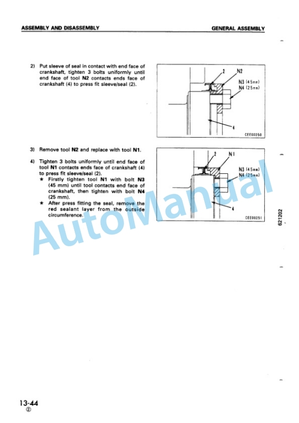
- 6.2.15. Front seal
- 6.2.16. Cam follower
- 6.2.17. Oil cooler assembly
- 6.2.18. Water pump assembly
- 6.2.19. Thermostat housing
- 6.2.20. Front support
- 6.2.21. Vibration damper, crankshaft pulley assembly
- 6.2.22. Cylinder head assembly
- 6.2.23. Crosshead
- 6.2.24. Rocker arm housing
- 6.2.25. Push rod
- 6.2.26. Rocker arm
- 6.2.27. Adjusting valve clearance
- 6.2.28. Nozzle holder, inlet connector
- 6.2.29. Rocker arm housing cover, spill pipe, air vent tube
- 6.2.30. Flywheel housing
- 6.2.31. Rear seal
- 6.2.32. Flywheel
- 6.2.33. Suction pipe
- 6.2.34. Oil pan
- 6.2.35. Oil filter assembly, oil regulator
- 6.2.36. Fuel filter assemblyfuel filter bracket
- 6.2.37. PTO case tube, bracket
- 6.2.38. Fuel injection pump assembly
- 6.2.39. Adjusting fuel injection pump
- 6.2.40. Fuel injection tube
- 6.2.41. Aftercooler assembly (Intake manifold assembly)
- 6.2.42. Exhaust manifold
- 6.2.43. Turbocharger
- 6.2.44. Fuel hose
- 6.2.45. Dipstick guide, air compressor
- 6.2.46. Alternator assembly, pulley
- 6.2.47. Fan pulley assembly
- 6.2.48. Tension pulley assembly
- 6.2.49. Intake connector
- 6.2.50. Muffler bracket, air cleaner bracket
- 6.2.51. Corrosion resistor
- 6.2.52. Resetting engine in engine stand
- 6.2.53. Turbocharger drain tube
- 6.2.54. Starting motor
- 6.2.55. Air cleaner, muffler
- 6.2.56. Refilling with oil
- 7. Maintenance standard
- 7.1. Intake and exhaust system
- 7.1.1. Turbocharger
- 7.2. Engine body
- 7.2.1. Cylinder head
- 7.2.2. Valve, valve guide
- 7.2.3. Rocker arm and shaft
- 7.2.4. Crosshead and guide
- 7.2.5. Cylinder block
- 7.2.6. Cylinder liner
- 7.2.7. Crankshaft
- 7.2.8. Camshaft
- 7.2.9. Cam follower and push rod
- 7.2.10. Timing gear
- 7.2.11. Piston
- 7.2.12. Connecting rod
- 7.2.13. Flywheel and flywheel housing
- 7.3. Lubrication system
- 7.3.1. Oil pump
- 7.3.2. Regulator valve, piston cooling valve and safety valve
- 7.3.3. Oil cooler
- 7.4. Cooling system
- 7.4.1. Water pump
- 7.4.2. Thermostat
- 8. Repair and replacement of parts
- 8.1. Table of special tools
- 8.2. Cylinder head
- 8.2.1. Grinding of fitting face ofcylinder head
- 8.2.2. Replacing valve seat insert
- 8.2.3. Pressure test
- 8.2.4. Replacing valve guide
- 8.2.5. Replacing crosshead guide
- 8.2.6. Grinding valve
- 8.3. Cylinder block
- 8.3.1. Replacing cam bushing
- 8.3.2. Replacing crankshaft gear
- 8.3.3. Replacing cam gear
- 8.3.4. Replacing flywheel ring gear
- 8.3.5. Replacing connecting rodsmall end bushing
- 8.3.6. Cylinder block parts
- 8.3.7. Testing and inspecting cylinder block
- 8.3.8. Correcting cylinder block top surface, counterbore
- 8.3.9. Replacing main bearing cap



There are no reviews yet.