
Description
-
Model List:
- 82E-5 Series Diesel Engine
- 98E-5 Series Diesel Engine
- 1. MAIN MENU
- 2. COVER
- 3. PREFACE
- 4. SAFETY LABELS
- 5. SAFETY PRECAUTIONS
- 6. PRECAUTIONS FOR SERVICE WORK
- 7. HOW TO READ THIS MANUAL
- 8. APPLICATION CATEGORY
- 9. APPLICABLE MACHINE, SERIAL NUMBER
- 10. CONTENTS
- 11. GENERAL
- 11.1. Specifications
- 11.2. Engine External Views
- 11.3. Structural Description
- 12. INSPECTION AND ADJUSTMENT
- 12.1. Periodic Maintenance Schedule
- 12.2. Periodic Inspection and Maintenance Procedure
- 12.3. Check before daily operation
- 12.4. Inspection after initial 50 hours operation
- 12.5. Inspection every 50 hours
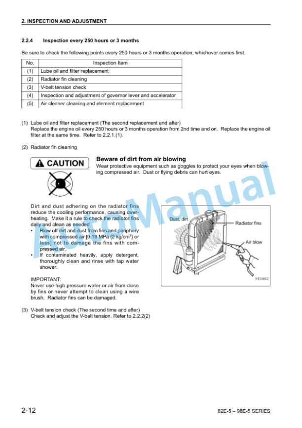
- 12.6. Inspection every 250 hours or 3 months
- 12.7. Inspection every 500 hours or 6 months
- 12.8. Inspection every 1,000 hours or one year
- 12.9. Inspection every 2000 hours or 2 years
- 12.10. Adjusting the Noload Maximum or Minimum Speed
- 12.11. Sensor Inspection
- 12.12. Oil pressure switch
- 12.13. Thermo switch
- 12.14. Water Leak Check in Cooling Water System
- 12.15. Radiator Cap Inspection
- 12.16. Thermostat Inspection
- 12.17. Adjusting Operation
- 12.18. Long Storage
- 13. TROUBLESHOOTING
- 13.1. Preparation Before Troubleshooting
- 13.2. Quick Reference Table for Troubleshooting
- 13.3. Troubleshooting by Measuring Compression Pressure
- 14. DISASSEMBLY, INSPECTION AND REASSEMBLY OF ENGINES
- 14.1. Complete Disassembly and Reassembly
- 14.2. Introduction
- 14.3. Special service tools
- 14.4. Complete disassembly
- 14.5. Precautions before and during reassembly
- 14.6. Adjusting operation
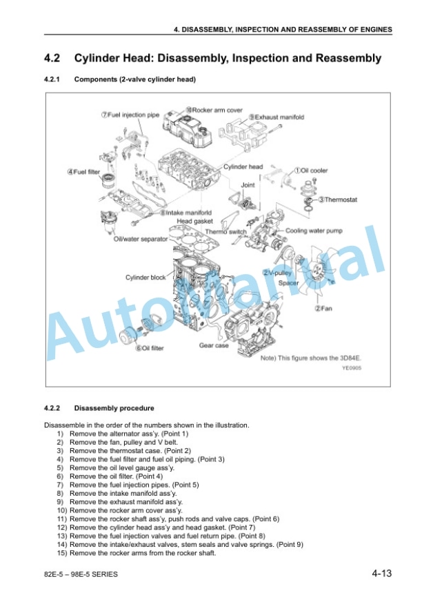
- 14.7. Cylinder Head Disassembly, Inspection and Reassembly
- 14.8. Components (2valve cylinder head)
- 14.9. Disassembly procedure
- 14.10. Reassembly procedure
- 14.11. Servicing points
- 14.12. Parts inspection and measurement
- 14.13. Valve seat correction
- 14.14. Valve guide replacement
- 14.15. Valve stem seal replacement
- 14.16. Gear Train and Camshaft
- 14.17. Components
- 14.18. Disassembly procedure
- 14.19. Reassembly procedure
- 14.20. Servicing points
- 14.21. Parts inspection and measurement
- 14.22. Oil seal replacement (Gear case side)
- 14.23. Camshaft bushing replacement
- 14.24. Cylinder Block
- 14.25. Components
- 14.26. Disassembly procedure
- 14.27. Reassembly procedure
- 14.28. Servicing points
- 14.29. Parts inspection and measurement
- 14.30. Cylinder bore correction
- 14.31. Piston pin bushing replacement
- 14.32. Oil seal replacement (Flywheel housing side)
- 15. LUBRICATION SYSTEM
- 15.1. Lubrication System Diagram
- 15.2. Trochoid Pump Components
- 15.3. Disassembly (Reverse the procedure below for assembly)
- 15.4. Servicing Points
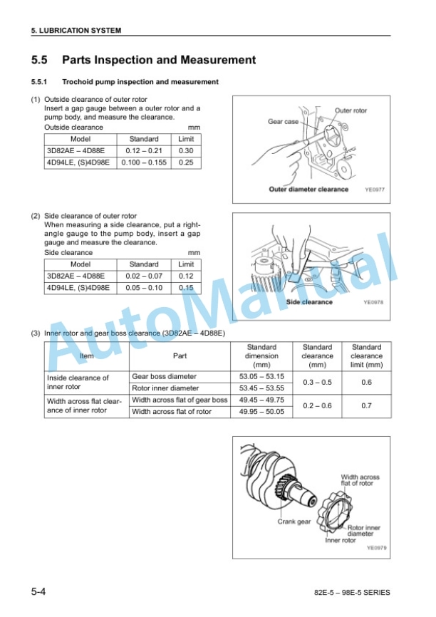
- 15.5. Parts Inspection and Measurement
- 16. COOLING SYSTEM
- 16.1. Cooling Water System
- 16.2. Cooling Water Pump Components
- 16.3. Disassembly (Reverse the procedure below for assembly)
- 16.4. Servicing Points
- 17. FUEL INJECTION PUMP/GOVERNOR
- 17.1. Introduction
- 17.2. Fuel Injection Pump
- 17.3. Fuel system diagram
- 17.4. External view and components
- 17.5. Disassembly procedure
- 17.6. Assembly procedure
- 17.7. Servicing points
- 18. TURBOCHARGER
- 18.1. Structure and Functions
- 18.2. Main specifications
- 18.3. Construction
- 18.4. Structural and functional outline
- 18.5. Components
- 18.6. Components
- 18.7. Service Standards and Tightening Torque
- 18.8. Service standards
- 18.9. Tightening torque
- 18.10. Periodic Inspection Procedure
- 18.11. Periodic inspection intervals
- 18.12. Inspection procedure
- 18.13. Waste gate valve adjustment procedure
- 18.14. Disassembly Procedure
- 18.15. Preparation for disassembly
- 18.16. Inspection before disassembly
- 18.17. Disassembly
- 18.18. Washing and Inspection Procedure
- 18.19. Washing
- 18.20. Inspection procedure
- 18.21. Reassembly Procedure
- 18.22. Preparation for reassembly
- 18.23. Reassembly
- 18.24. Handling after Disassembly and Reassembly
- 18.25. Instructions for turbocharger installation
- 18.26. Troubleshooting
- 18.27. Excessively exhaust smoke
- 18.28. White smoke generation
- 18.29. Sudden oil decrease
- 18.30. Decrease in output
- 18.31. Poor (slow) response (starting) of turbocharger
- 18.32. Abnormal sound or vibration
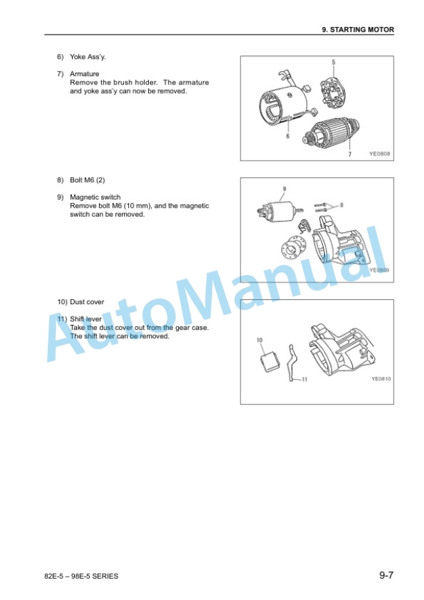
- 19. STARTING MOTOR
- 19.1. For 4D94LE/(S)4D98E
- 19.2. Specifications
- 19.3. Components
- 19.4. Troubleshooting
- 19.5. Names of parts and disassembly procedure
- 19.6. Inspection and maintenance
- 19.7. Service standards
- 19.8. Assembly
- 19.9. Characteristic test
- 20. ALTERNATOR
- 20.1. The 40A Alternator for 3D84E and Other Models
- 20.2. Components
- 20.3. Specifications
- 20.4. Wiring diagram
- 20.5. Standard output characteristics
- 20.6. Inspection
- 20.7. Troubleshooting
- 21. ELECTRIC WIRING
- 21.1. Electric Wiring Diagram
- 21.2. Precaution on Electric Wiring
- 21.3. Alternator
- 21.4. Starting motor
- 21.5. Current limiter
- 21.6. Section area and resistance of electric wire
- 22. SERVICE STANDARDS
- 22.1. Engine Tuning
- 22.2. Engine Body
- 22.3. Cylinder head
- 22.4. Gear train and camshaft
- 22.5. Cylinder block
- 22.6. Lubricating Oil System (Trochoid Pump)
- 23. TIGHTENING TORQUE FOR BOLTS AND NUTS
- 23.1. Tightening Torques for Main Bolts and Nuts
- 23.2. Tightening Torques for Standard Bolts and Nuts


There are no reviews yet.