
Description
-
Model List:
- 95 Series Engine
- 1. SEN0440800 WA656, WA706, WA806
- 1.1. General assembly drawing
- 1.2. WE5 LEFT SIDE VIEW (WA65HH6)
- 1.3. WE5 RIGHT SIDE VIEW (WA65HH6)
- 1.4. WE5 FRONT VIEW (WA65HH6)
- 1.5. WE5 REAR VIEW (WA65HH6)
- 1.6. S4D95LWE5 LEFT SIDE VIEW (WA80HH6)
- 1.7. S4D95LWE5 RIGHT SIDE VIEW (WA80HH6)
- 1.8. S4D95LWE5 FRONT VIEW (WA80HH6)
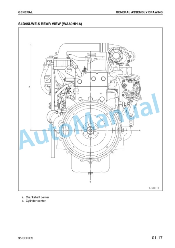
- 1.9. S4D95LWE5 REAR VIEW (WA80HH6)
- 1.10. DIMENSION TABLE
- 1.11. Engine performance curve
- 1.12. WE5 Applicable machine WA65HH6
- 1.13. WE5 Applicable machine WA70HH6
- 1.14. WE5 Applicable machine WA80HH6
- 1.15. Weight table
- 2. STRUCTURE AND FUNCTION
- 2.1. General structure
- 2.2. EXHAUST SYSTEM
- 2.2.1. Turbocharger
- 2.2.2. TD04L
- 2.2.2.1. Outline of waste gate valve
- 2.2.3. Main moving parts
- 2.2.4. Timing gear
- 2.2.5. WITHOUT FRONT PTO TYPE (HELICAL GEAR)
- 2.2.5.1. Front oil seal
- 2.2.6. Valve system
- 2.2.7. Flywheel and flywheel housing
- 2.2.8. WITHOUT REAR PTO TYPE
- 2.3. LUBRICATION SYSTEM
- 2.3.1. Lubrication system chart
- 2.3.2. Oil pump
- 2.3.2.1. Specifications
- 2.3.2.2. Oil pump
- 2.3.2.3. Regulator valve
- 2.3.3. Oil filter
- 2.3.3.1. Relief valve
- 2.4. FUEL SYSTEM
- 2.4.1. Fuel system chart
- 2.4.2. Fuel injection pump
- 2.4.3. Fuel injection nozzle
- 2.4.4. For direct fuel injection type
- 2.4.5. For swirl chamber type
- 2.4.5.1. Fuel injection nozzle
- 2.5. COOLING STSTEM
- 2.5.1. Cooling system chart
- 2.5.2. Thermostat and fan drive
- 2.5.3. THERMOSTAT (WITHOUT JIGGLE VALVE)
- 2.6. ELECTRICAL SYSTEM
- 2.6.1. Starting and charging system electrical circuit diagram
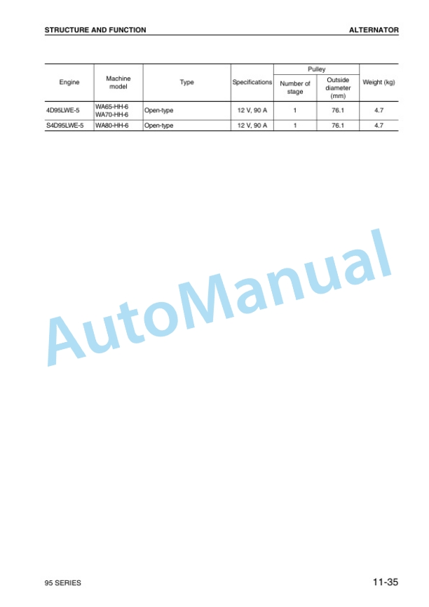
- 2.6.2. Alternator
- 2.6.3. ALTERNATOR WITH BUILTIN REGULATOR (Open type, 90A)
- 2.6.4. Starting motor
- 2.6.4.1. For 2.2 kW
- 2.6.5. Engine starting device
- 2.6.6. GLOW PLUG (METAL 2WIRE TYPE GLOW PLUG)
- 2.6.6.1. Connector (round 8pin), (Short 8pin)
- 2.6.6.2. Lead wire
- 2.6.6.3. Case
- 2.6.6.4. Bracket
- 2.6.6.5. Label
- 2.6.6.6. Water temperature sensor
- 2.6.6.7. Glow relay
- 2.6.6.8. Lead wire
- 2.6.6.9. Connector (round 2in)
- 3. TESTING AND ADJUSTING
- 3.1. Performance test
- 3.2. Runin standard
- 3.3. Performance test criteria
- 3.4. Testing and adjusting data
- 3.5. Testing and adjusting tools list
- 3.6. Intake and exhaust system
- 3.7. Adjusting valve clearance
- 3.8. Engine body
- 3.9. Measuring compression pressure
- 3.9.1. Measurement procedure
- 3.10. Fuel system
- 3.11. Adjusting fuel injection pressure (Cracking pressure)
- 3.12. Shim data for adjusting injection pressure
- 3.13. Testing and adjusting fuel injection timing
- 3.14. Table of injection pumps using plunger with stepped lead
- 3.15. Adjusting fuel injection rate
- 3.16. Governor adjustment standard
- 3.17. Troubleshooting
- 3.18. Method of using troubleshooting charts
- 3.19. Points on troubleshooting
- 3.20. S1 Starting performance is poor (Starting always takes time)
- 3.21. S2 Engine does not start
- 3.21.1. Engine does not turn
- 3.21.2. Engine turns but no exhaust gas comes out (Fuel is not being injected)
- 3.21.3. Exhaust gas comes out but engine does not start (Fuel is being injected)
- 3.22. S3 Engine does not pick up smoothly (Followup is poor)
- 3.23. S4 Engine stops during operations
- 3.24. S5 Engine does not rotate smoothly
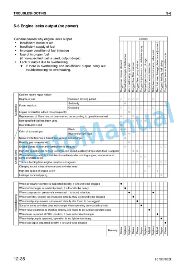
- 3.25. S6 Engine lacks output (no power)
- 3.26. S7 Exhaust gas is black (incomplete combustion)
- 3.27. S8 Oil consumption is excessive (or exhaust gas is blue)
- 3.28. S9 Oil becomes contaminated quickly
- 3.29. S10 Fuel consumption is excessive
- 3.30. S11 Oil is in coolant, or coolant spurts back, or coolant level goes down
- 3.31. S12 Oil pressure lamp lights up (drop in oil pressure)
- 3.32. S13 Oil level rises
- 3.33. S14 Coolant temperature becomes too high (overheating)
- 3.34. S15 Abnormal noise is made
- 3.35. S16 Vibration is excessive
- 4. DISASSEMLY AND ASSEMBLY
- 4.1. General disassembly
- 4.1.1. Special tools
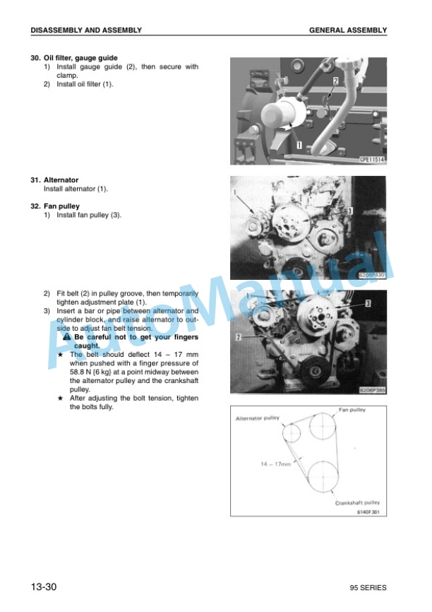
- 4.2. General assembly
- 4.2.1. Special tools
- 5. MAINTENANCE STANDARD
- 5.1. Turbocharger
- 5.2. Cylinder head
- 5.3. Valve, valve guide
- 5.4. Rocker arm shaft, push rod and tappet
- 5.5. Cylinder block
- 5.6. Cylinder
- 5.7. Crankshaft
- 5.8. Camshaft
- 5.9. Timing gear (Helical gear)
- 5.10. Flywheel and flywheel housing
- 5.11. Piston, piston ring and piston pin
- 5.12. Connecting rod
- 5.13. Regulator valve
- 5.14. Water pump and thermostat
- 6. REPAIR AND REPLACEMENT OF PARTS
- 6.1. Grinding cylinder head mounting surface
- 6.2. Replacing valve guide
- 6.2.1. Special tools
- 6.3. Grinding valve
- 6.3.1. Special tool
- 6.4. Replacing camshaft bushing
- 6.4.1. Special tools
- 6.5. Replacing crankshaft gear
- 6.6. Testing and adjusting fuel injection timing
- 6.7. Replacing flywheel ring gear
- 6.8. Procedure for pressure test
- 6.8.1. Special tools
- 6.9. Cylinder liner
- 6.10. (special restoration part)
- 6.10.1. Cylinder liner
- 6.11. Machining drawing for cylinder block bore
- 6.12. Additional machining of cam journal
- 6.13. Grinding crankshaft
- 6.13.1. Applicable crankshaft
- 6.14. Replacing connecting rod small end bushing
- 6.14.1. Special tools



There are no reviews yet.