
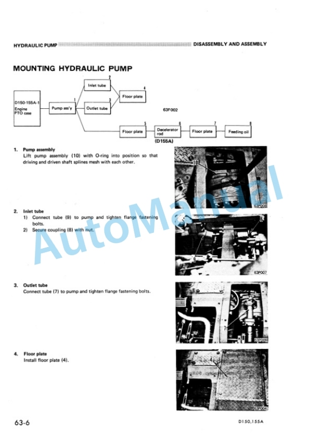
Description
-
Model List:
- D150A-1
- D155A-1
- 2. Contents
- 3. Safety
- 3.1. How to read the shop manual
- 3.2. Hoisting instructions
- 3.3. Standard tightening torque
- 4. General
- 4.1. Specifications
- 4.2. General assembly drawing
- 4.3. Engine specifications
- 4.4. Weight table
- 4.5. Position of serial numbers (Engine)
- 4.6. Position of serial numbers (body)
- 4.7. Table of oil and coolant
- 5. Engine structure and function
- 6. Engine Testing and adjusting
- 6.1. Tool list
- 6.2. Trouble shooting criteria
- 6.3. General instructions
- 6.4. Intake ans exhaust system
- 6.5. Engine body
- 6.6. Lubrication system
- 6.7. Fuel system
- 7. Engine disassembly and assembly
- 7.1. Dismounting turbocharger
- 7.2. mounting turbocharger
- 7.3. Dismounting engine oil cooler
- 7.4. Mounting engine oil cooler
- 7.5. torque convertor oil cooler
- 7.6. Nozzle holder
- 7.7. Fuel injection pump
- 8. Power traing Structure and functions
- 8.1. General
- 8.2. Main clutch
- 8.3. Inertia brake
- 8.4. Transmisssion D150A
- 8.5. Double mesh preventive device
- 8.6. Torque convertor
- 8.7. Transmission D155A
- 8.8. Torqflow
- 8.9. Transmission lubrication relief vanlve
- 8.10. Transmission control valve
- 8.11. Transmission pump
- 8.12. Bevel gear shaft and steering clutch
- 8.13. Steering and brake piping
- 8.14. steering hydraulic system
- 8.15. Brake hydraulic system
- 8.16. Steering brake and booster D150A AND D155A
- 8.16.1. Steering control valve
- 8.16.2. Steering and brake piping
- 8.16.3. Steering and brake hydraulic circuit
- 8.17. Steering brake and booster D155A 25001
- 8.18. Steering control valve d155a 25001
- 8.19. Steering pump
- 8.20. Final drive
- 9. power train testing and adjusting
- 9.1. Main clutch hydraulic control
- 9.2. Torqflow hydraulic control
- 9.3. Steering hydraulic control
- 9.4. Brake hydraulic control
- 9.5. Table of oil pressure measuring points
- 9.6. Procedure for measuring oil pressure and temperature
- 9.7. Procedure for measurment of lever and pedal travel
- 9.8. Adjustment procedure for strokes
- 9.9. Adjusting main clutch
- 9.10. Table of maintenance standerds
- 10. Power train disassembly and assembly
- 10.1. pto and flywheel
- 10.2. Main clutch
- 10.3. Transmission assembly
- 10.4. Torque convertor
- 10.5. Torque convertor relief valve
- 10.6. Torque converter regulator valve
- 10.7. Torqflow transmission D155 15001 25000
- 10.8. Torqflow transmission D155A Sn 25001
- 10.8.1. Mounting Torqflow transmission
- 10.8.2. Dismounting Transmission control valve
- 10.8.3. Mounting transmission control valve
- 10.8.4. Transmission lubrication valve
- 10.8.5. Steering clutch
- 10.9. Bevel gear and bevel gear shaft
- 10.10. Final drive
- 10.11. Steering control valve
- 10.12. Steering brake interlocking valve
- 10.13. Brake safety valve
- 10.14. Brake booster
- 10.15. Final drive
- 10.16. Torqflow pump
- 10.17. Steering pump
- 10.18. Torque converter oil cooler
- 11. Power Train Maintenance standard
- 11.1. Transmission
- 11.2. Bevel gear shaft and steering system
- 11.3. Final drive
- 12. Undercarriage Structure and function
- 12.1. Track
- 12.2. Track group
- 12.3. Recail spring
- 12.4. Idler
- 12.5. Track roller, carrier roller
- 12.6. Suspension
- 13. undercarriage Testing and adjusting
- 14. indercarriage Disassembly and assembly
- 15. Undercarriage maintenance standard
- 15.1. Undercarriage
- 16. Hydraulic system structure and function
- 16.1. Hydraulic control
- 16.2. Hydraulic tank
- 16.3. Hydraulic control valve
- 16.4. Ripper selector valve and pilot check valve
- 16.5. Pin puller valve
- 16.6. Pilot valve
- 16.7. Rotary servo valve
- 16.8. Servo valve hydralic control/valve
- 16.9. Safety valve
- 16.10. Cylinders
- 16.11. Piston valve
- 16.12. Hydraulic control
- 17. Hydraulic system testing and adjusting
- 17.1. General description
- 17.2. Hydraulic control
- 17.3. Pin puller control
- 17.4. Measurment of oil pressure and temperature
- 17.5. Measurment of operating force
- 17.6. Table of maintance standard
- 18. Hydraulic control sysyem Disassembly and assembly
- 18.1. Disassembly and assembly
- 18.2. Hydraulic pump
- 18.3. Hydraulic tank
- 18.4. Ripper blade control valve
- 18.5. Blade tilt control valve
- 18.6. Blade tilt servo valve
- 18.7. Ripper servo valve
- 18.8. Ripper pin puller valve
- 18.9. Ripper selector valve
- 18.10. Blade lift cylinder
- 18.11. Blade tilt cylinder
- 18.12. Ripper lift Tilt cylinder
- 18.13. Ripper pin puller cylinder
- 19. Hydraulic system Maintance standard
- 19.1. Torque specifications for nuts and bolts
- 19.2. Hydraulic control valve
- 19.3. Cylinders
- 20. Work equipment structure and function
- 20.1. Multi ripper
- 20.2. Giant ripper
- 21. Work equipment testing and adjustment
- 21.1. Straight tilt dozer
- 22. work equipment disassembly assembly
- 22.1. Blade
- 22.2. Ripper
- 23. Work equipment Maintenance standard
- 23.1. Torque specifications
- 23.2. Straight tilt dozer
- 23.3. Multi ripper
- 23.4. Giant ripper
- 24. Others Electrical system
- 24.1. Electical circuit diagram
- 24.2. Electical wiring diagram
- 24.3. Warning module
- 24.4. Automatic priming system


There are no reviews yet.