
Description
-
Model List:
- D61EX-15 Bull Dozer
- D61PX-15 Bull Dozer
- 1. MAIN MENU
- 2. COVER
- 3. TABLE OF GENERAL CONTENTS
- 4. GENERAL FOREWARD
- 4.1. SAFETY
- 4.2. FOREWARD
- 5. GENERAL
- 5.1. Specification dimension drawing
- 5.2. Specifications
- 5.3. Weight table
- 5.4. Oil and coolant table
- 6. GENERAL STRUCTURE AND FUNCTION, MAINTENANCE STANDARD
- 6.1. Engine and cooling related components
- 6.1.1. Cooling system
- 6.2. Power transmitting system
- 6.2.1. Power train
- 6.2.2. Power train skeleton
- 6.2.3. Overall drawing of power train unit
- 6.2.4. Hydraulic piping diagram of power train
- 6.2.5. Damper and universal joint
- 6.2.6. Transmission, steering, and brake control
- 6.3. Power transmitting system
- 6.3.1. Torque converter and PTO
- 6.3.2. Transmission
- 6.3.3. Transmission ECMV
- 6.3.4. Main relief valve
- 6.3.5. Lubricating oil relief valve
- 6.4. Power transmitting system
- 6.4.1. Scavenging pump
- 6.4.2. Power train and lubrication pump
- 6.4.3. HSS system
- 6.5. Power transmitting system
- 6.5.1. HSS pump
- 6.5.2. HSS motor
- 6.6. Power transmitting system
- 6.6.1. Bevel gear shaft, HSS, and brake
- 6.6.2. Brake valve
- 6.6.3. Final drive
- 6.7. Undercarriage and frame
- 6.7.1. Frame assembly
- 6.7.2. Suspension
- 6.7.3. Track frame and recoil spring
- 6.8. Hydraulic system
- 6.8.1. Layout of hydraulic devices for work equipment
- 6.8.2. Work equipment control
- 6.8.3. Hydraulic tank and filter
- 6.8.4. Solenoid valve
- 6.8.5. Accumulator
- 6.8.6. Hydraulic cylinder
- 6.8.7. Piston valve
- 6.8.8. Quick drop valve
- 6.9. Hydraulic system
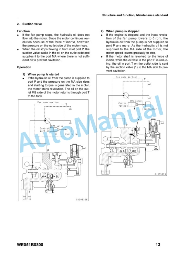
- 6.9.1. Cooling fan pump
- 6.9.2. Cooling fan motor
- 6.9.3. PPC valve
- 6.9.4. Electric lever (Steering)
- 6.10. Hydraulic system
- 6.10.1. Control valve
- 6.10.2. CLSS
- 6.10.3. Selfpressure reducing valve
- 6.11. Work equipment
- 6.11.1. Work equipment
- 6.11.2. Cutting edge and end bit
- 6.11.3. Ripper
- 6.12. Cab and its attachments
- 6.12.1. Cab mount
- 6.12.3. Air conditioner piping
- 6.13. Electric system
- 6.13.1. Engine control system
- 6.13.2. Cooling system control system
- 6.13.3. Palm command control system
- 6.13.4. PPC lock system
- 6.13.5. Component parts of system
- 6.13.6. Monitor system
- 6.13.7. Monitor panel
- 6.13.8. Sensor
- 7. TESTING, ADJUSTING TROUBLESHOOTING
- 7.1. Standard value table
- 7.1.1. Standard value table for engine
- 7.1.2. Standard value table for chassis
- 7.2. Testing and adjusting
- 7.2.1. Testing and adjusting (1/2)
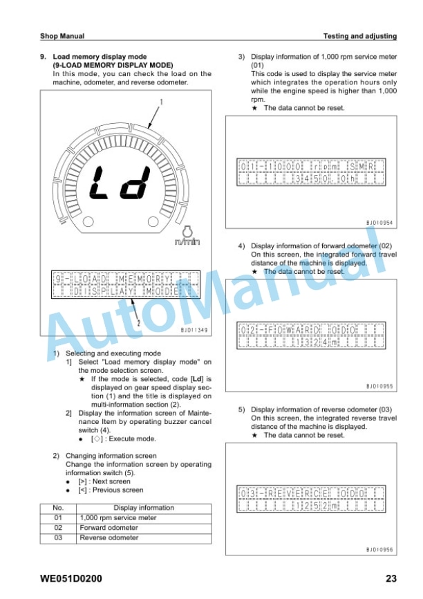
- 7.2.2. Testing and adjusting (2/2)
- 7.3. Troubleshooting
- 7.3.1. Preface
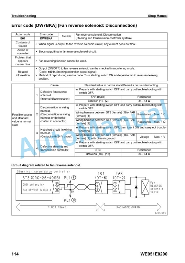
- 7.3.2. Troubleshooting when error code is displayed (Error code) CONTENTS
- 7.3.3. Troubleshooting of electrical system (Emode) CONTENTS
- 7.3.4. Troubleshooting of hydraulic and mechanical system (Hmode) CONTENTS
- 7.3.5. Troubleshooting of engine system (Smode) CONTENTS
- 8. DISASSEMBLY AND ASSEMBLY
- 8.1. Preface
- 8.1.1. How to read this manual
- 8.1.2. Standard tightening torque table
- 8.1.3. Precautions when performing operation
- 8.1.4. List of coatings
- 8.1.5. Special tool list
- 8.1.6. Sketches of special tools
- 8.2. Engine related procedures
- 8.2.1. Removal and installation of fuel injection pump assembly
- 8.2.2. Removal and installation of cylinder head assembly
- 8.2.3. Removal and installation of engine front seal
- 8.2.4. Removal and installation of engine rear seal
- 8.2.5. Removal and installation of engine assembly
- 8.2.6. Removal and installation of damper assembly
- 8.2.7. Removal and installation of radiator guard assembly
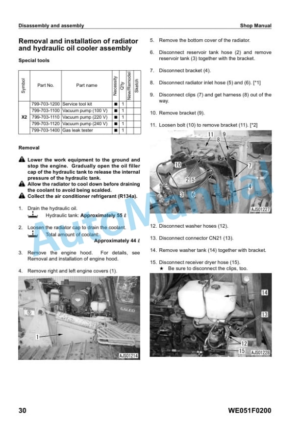
- 8.2.8. Removal and installation of radiator and hydraulic oil cooler assembly
- 8.2.9. Removal and installation of fan drive assembly
- 8.2.10. Removal and installation of fan motor assembly
- 8.2.11. Removal and installation of engine hood assembly
- 8.2.12. Removal and installation of fuel tank assembly
- 8.3. Power train
- 8.3.1. Removal and installation of PTO, torque converter and transmission assembly
- 8.3.2. Disconnection and connection of PTO, torque converter and transmission assembly
- 8.3.3. Disassembly and assembly of PTO assembly
- 8.3.4. Disassembly and assembly of torque converter assembly
- 8.3.5. Disassembly and assembly of TORQFLOW transmission assembly
- 8.3.6. Removal and installation of torque converter main relief valve assembly
- 8.3.7. Disassembly and assembly of torque converter main relief valve assembly
- 8.4. Power train
- 8.4.1. Removal and installation of power train and lubricating oil pump assembly
- 8.4.2. Removal and installation of HSS and work equipment pump assembly
- 8.4.3. Removal and installation of scavenging pump assembly
- 8.4.4. Removal and installation of HSS motor assembly
- 8.4.5. Disassembly and assembly of HSS assembly
- 8.4.6. Removal and installation of final drive assembly
- 8.4.7. Disassembly and assembly of final drive assembly
- 8.5. Undercarriage
- 8.5.1. Removal and installation of track frame assembly
- 8.5.2. Removal and installation of idler assembly
- 8.5.3. Disassembly and assembly of idler assembly
- 8.5.4. Removal and installation of recoil spring assembly
- 8.5.5. Disassembly and assembly of recoil spring assembly
- 8.5.6. Removal and installation of track roller assembly
- 8.5.7. Disassembly and assembly of track roller assembly
- 8.5.8. Removal and installation of carrier roller assembly
- 8.5.9. Disassembly and assembly of carrier roller assembly
- 8.6. Undercarriage
- 8.6.1. Check before expanding track shoe assembly
- 8.6.2. Expansion (normal), expansion (internal abnormality) and installation of track shoe assembly
- 8.6.3. Overall disassembly and overall assembly of track shoe assembly
- 8.6.4. Link pressfitting jig dimensions table
- 8.6.5. Field disassembly and assembly of one link
- 8.6.6. Removal and installation of pivot shaft assembly
- 8.6.7. Removal and installation of equalizer bar assembly
- 8.6.8. Removal and installation of equalizer bar side bushing
- 8.6.9. Removal and installation of segment teeth
- 8.7. Hydraulic system
- 8.7.1. Removal and installation of main control valve assembly
- 8.7.2. Assembly of main control valve assembly
- 8.7.3. Removal and installation of cooling fan pump assembly
- 8.7.4. Removal and installation of work equipment assembly
- 8.7.5. Disassembly and assembly of work equipment assembly
- 8.7.6. Disassembly and assembly of hydraulic cylinder assembly
- 8.8. Others
- 8.8.1. Removal and installation of operators cab assembly
- 8.8.2. Removal and installation of operators cab glass (stuck glass)
- 8.8.3. Removal and installation of ROPS canopy
- 8.8.4. Removal and installation of dashboard assembly
- 8.8.5. Removal and installation of floor frame assembly
- 8.8.6. Removal and installation of steering and transmission controller assembly
- 9. OTHERS
- 9.1. Hydraulic circuit diagram
- 9.1.1. Power train hydraulic circuit diagram
- 9.1.2. Work equipment hydraulic circuit diagram Power angle power tilt dozer (PAT)
- 9.1.3. Work equipment hydraulic circuit diagram Power tilt dozer (PT)
- 9.2. Electrical circuit diagram
- 9.2.1. Electrical circuit diagram (1/6)
- 9.2.2. Electrical circuit diagram (2/6)
- 9.2.3. Electrical circuit diagram (3/6)
- 9.2.4. Electrical circuit diagram (4/6)
- 9.2.5. Electrical circuit diagram (5/6)
- 9.2.6. Electrical circuit diagram (6/6)
- 9.2.7. Cab electrical circuit diagram



There are no reviews yet.