
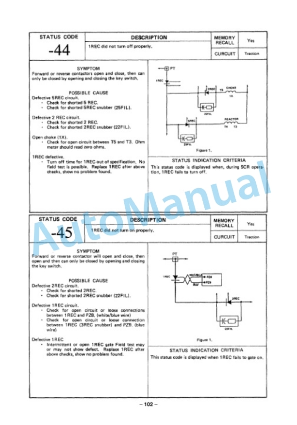
Description
-
Model List:
- FB15SH-6 Electric Lift Truck
- FB18SH-6 Electric Lift Truck
- 1. AHFORE
- 1.1. FOREWORD
- 2. AHGEN
- 2.1. GENERAL AND SPECIFICATIONS
- 2.1.1. Overall dimensions and specifications
- 2.1.2. Weight of main components
- 2.1.3. Standard tightening torque for bolts
- 2.1.4. Standard tightening torque for pipe joints
- 2.1.5. Periodical replacement of safetyassuring parts
- 2.1.6. General locations
- 2.1.7. Instruments and controls
- 3. AHCONV
- 3.1. CONVERSION TABLE
- 3.1.1. Millimeters to Inches
- 3.1.2. Inches to millimeters
- 3.1.3. Cubic meters to Cubic yards
- 3.1.4. Cubic yards to Cubic meters
- 3.1.5. Liters to U.S. Gallon
- 3.1.6. Gallon to Liter
- 3.1.7. Liter to U.K. Gallon
- 3.1.8. Gallon to Liter
- 3.1.9. Kilogram to Pound
- 3.1.10. Pound to Kilogram
- 3.1.11. kg/cm to lb/in
- 3.1.12. Kgm to Ft. lb
- 3.1.13. Temperature
- 4. AHDIS
- 4.1. DISASSEMBLY AND ASSEMBLY OF COMPONENTS
- 4.1.1. POWER TRAIN
- 4.1.1.1. Transfer
- 4.1.1.2. Wheel brake
- 4.1.1.3. Differential
- 4.1.1.4. Drive axle
- 4.1.2. BRAKE SYSTEM
- 4.1.2.1. Master cylinder
- 4.1.2.2. Wheel brake
- 4.1.2.3. Air vent
- 4.1.3. STEERING SYSTEM
- 4.1.3.1. Power steering valve
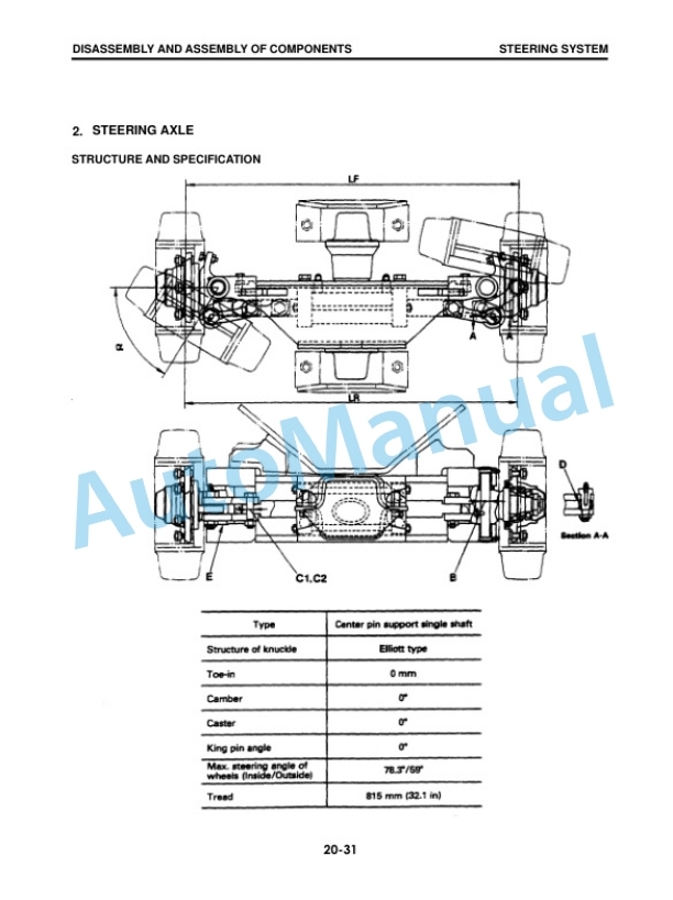
- 4.1.3.2. Steering axle
- 4.1.3.3. Power steering cylinder
- 4.1.4. HYDRAULIC SYSTEM
- 4.1.4.1. Hydraulic circuit diagram
- 4.1.4.2. Hydraulic pump
- 4.1.4.3. Control valve
- 4.1.4.4. Control valve lever
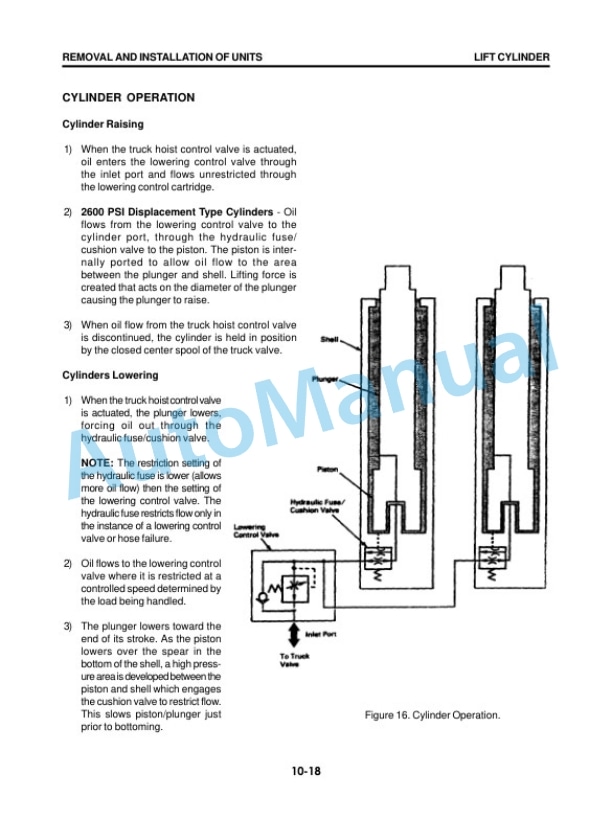
- 4.1.4.5. Lift cylinder (For Komatsumade mast)
- 4.1.4.6. Tilt cylinder
- 4.1.5. MAST
- 4.1.5.1. Mast (Komatsumade)
- 4.1.5.2. Mast (Cascademade)
- 5. AHELEC
- 5.1. ELECTRICAL SYSTEM
- 5.2. ELECTRICAL COMPONENTS
- 5.3. Digital multimeter
- 5.4. BATTERY AND CASE
- 5.5. Battery compartment
- 5.6. Notes on selecting a battery
- 5.7. Recommended batteries
- 5.8. MOTORS
- 6. AHREMOV
- 6.1. REMOVAL AND INSTALLATION OF UNITS
- 6.1.1. Locations of units
- 6.1.2. How to install units
- 6.1.3. Removal and installation flowcharts
- 6.1.4. Removal and installation of units
- 6.1.4.1. Mast (Komatsumade)
- 6.1.4.2. Lift cylinder (Komatsumade)
- 6.1.4.3. Mast (Cascademade)
- 6.1.4.4. Lift cylinder (Cascademade)
- 6.1.4.5. Power train (Drive axle, Transfer and Traction motor)
- 6.1.4.6. Pump motor
- 6.1.4.7. Power steering motor
- 6.1.4.8. Steering axle
- 6.1.4.9. Power steering cylinder
- 7. AHTEST
- 7.1. TESTING AND ADJUSTING
- 7.1.1. Motor
- 7.1.2. Battery
- 7.1.3. Controller
- 7.1.4. Travel system
- 7.1.5. Steering system
- 7.1.6. Brake system
- 7.1.7. Work equipment system
- 7.1.8. Adjustment of parking brake lever
- 7.1.9. Adjustment of brake pedal
- 7.1.10. Adjustment of accelerator pedal
- 7.1.11. Adjustment of operators seat switch
- 8. AISM013
- 8.1. GENERAL MAINTENANCE INSTRUCTIONS
- 8.2. A COMPARISON OF GE EV100LXT CONTROLLER WITH THE EXISTING CONTROLLER
- 8.3. HANDSET SETTINGS ON MACHINES SHIPPED FROM FACTORY
- 8.4. LIST OF FUNCTION, EV100LXT TRACTION CONTROLLER FOR ABX
- 8.5. MAIN SPECIFICATIONS OF MOTOR AND SERVICE DATA
- 8.6. BASICS OF CIRCUIT OPERATION
- 8.7. OUTLINE OF CONTROLLER
- 8.7.1. Description of Control Functions
- 8.7.2. Dimensions of Traction SCR Panel
- 8.7.3. External View of Traction SCR Panel
- 8.7.4. Wiring of Traction SCR Panel
- 8.7.5. Contactor Panel
- 8.7.6. Accelerator
- 8.8. HYDRAULIC PUMP OPERATION (Contactor Type)
- 8.9. DEADMAN HORN ALARM CIRCUIT
- 8.10. GLOSSARY
- 8.11. ELEMENTARY DIAGRAM SYMBOLS
- 8.12. PROCDURES FOR REPLACING CONTROLLER COMPONENT PARTS
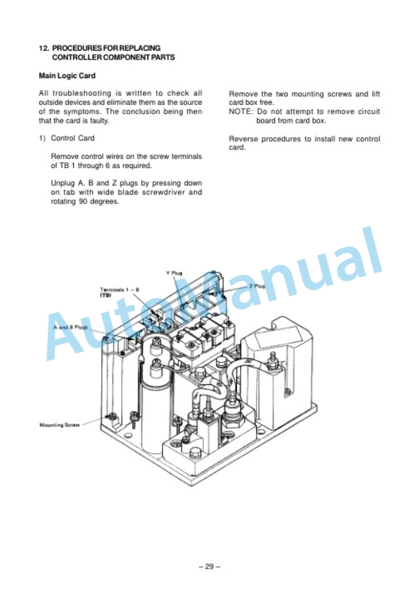
- 8.12.1. Control Card
- 8.12.2. Stud semiconductors
- 8.12.3. Capacitor
- 8.12.4. FIL, 23FIL, 24FIL, and 25FIL
- 8.12.5. Reactor/Choke
- 8.13. TROUBLESHOOTING
- 8.13.1. Digital Multifunction Displayer
- 8.13.2. Troubleshooting Instructions
- 8.13.3. Status Codes Requiring Troubleshooting by Use of Meter Panel
- 8.13.4. Procedure for Setting Travel Characteristics with HANDSET
- 8.14. SEQUENCE OF OPERATION
- 8.15. List of Status Codes
- 8.16. Troubleshooting for the Hydraulic Control with Contactor Type
- 8.16.1. The voltage reading at the terminals of PATD, PBTD and PAD, PBD wire
- 8.16.2. in normal conditions
- 8.16.3. Troubleshooting of hydraulic pump motor
- 8.16.3.1. Contactor closes and the pump motor does not rotate
- 8.16.3.2. The contactor does not close
- 8.16.3.3. No time delay after the valve switch open or the contactor tips chatters
- 8.17. Troubleshooting for the Horn Function
- 8.17.1. The voltage reading at the terminalsTMM2 normal conditions
- 8.17.2. Troubleshooting for the horn alarm function
- 8.17.2.1. The horn does not blow when the button is activated
- 8.17.2.2. The horn does blow with the condition listed below
- 8.17.2.3. The horn blows continuously
- 8.18. Troubleshooting of Power Steering Motor
- 8.18.1. Troubleshooting
- 8.18.2. Disassembly
- 8.18.3. Reassembly
- 8.19. Troubleshooting of the Brush for Traction and Pump Motors
- 8.20. Troubleshooting without use of the Meter Panel for Traction SCR Controller
- 8.20.1. The voltage reading at the terminalsin normal condition
- 8.20.2. Troubleshooting Instructions
- 8.21. All Testing should be Done with Truck Jacked Up
- 8.21.1. Failures that cause reduced or no motor torque with SCR control
- 8.21.2. Failures that cause full or no motor torque with SCR control
- 8.21.3. Misoperation of other features
- 8.22. Others Electrical component Parts
- 8.22.1. Capacitor 1C
- 8.22.2. Contactors F, R, 1 A and P
- 8.22.3. Potentiometer in accelerator
- 8.22.4. Coil driver module
- 8.22.5. SCRS (1 REC, 2REC, 5REC)
- 8.22.6. Rectifiers (3REC,2REC, diode blocks)
- 8.22.7. Thermal protector(TP)
- 8.22.8. Filter block (23FIL, etc)
- 8.22.9. choke and reactor T3T4
- 8.23. TROUBLESHOOTING (SYMPTOM CHART)
- 8.23.1. Field Weakening(F/W) Control System
- 8.24. CIRCUIT DIAGRAM


There are no reviews yet.