
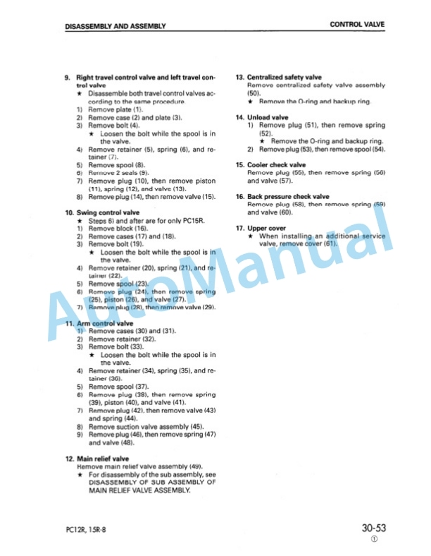
Description
-
Model List:
- PC12R-8 Hydraulic Excavator
- PC15R-8 Hydraulic Excavator
- 0.1. General assembly drawing
- 0.2. Specifications
- 0.3. List of lubricant and water
- 1. STRUCTURE AND FUNCTION
- 1.1. Power Train
- 1.2. Swing circle
- 1.3. Track frame and recoil spring
- 1.4. Hydraulic piping
- 1.5. Hydraulic tank
- 1.6. Hydraulic pump
- 1.7. Control valve (PC12R8)
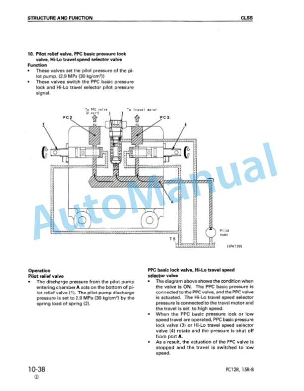
- 1.8. CLSS (PC12R8)
- 1.9. Control valve (PC15R8)
- 1.10. CLSS (PC15R8)
- 1.11. Center swivel joint
- 1.12. Machine monitor system
- 2. TESTING AND ADJUSTING
- 2.1. STANDARD VALUE TABLE
- 2.2. Standard value table for engine related parts
- 2.3. Standard value table for chassis related parts
- 2.4. Standard value table for electrical parts
- 2.5. TESTING AND ADJUSTING
- 2.5.1. Tools for testing, adjusting, and troubleshooting
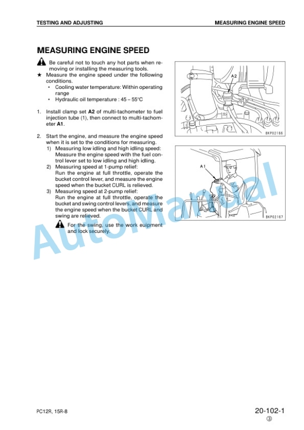
- 2.5.2. Measuring engine speed
- 2.5.3. Measuring exhaust color
- 2.5.4. Adjusting valve clearance
- 2.5.5. Measuring compression pressure
- 2.5.6. Testing and adjusting fuel injection timing
- 2.5.7. Measuring engine oil pressure
- 2.5.8. Testing and adjusting fan belt tension
- 2.5.9. Testing and adjusting fuel control lever
- 2.5.10. Measuring sprocket wear
- 2.5.11. Testing and adjusting track shoe tension
- 2.5.12. Testing and adjusting hydraulic pressure in work equipment, swing, travel circuit
- 2.5.13. Testing and adjusting LS differential pressure
- 2.5.14. Adjusting PC valve spring
- 2.5.15. Testing and adjusting control circut pressure
- 2.5.16. Measuring output pressure of PPC lock valve and travel boost valve
- 2.5.17. Testing PPC valve output pressure and swing holding brake inlet port pressure
- 2.5.18. Adjusting work equipment, swing PPC valve
- 2.5.19. Testing and adjusting travel deviation
- 2.5.20. Measuring oil leakage inside work equipment cylinder
- 2.5.21. Releasing remaining pressure from hydraulic circuit
- 2.5.22. Releasing remaining pressure from hydraulic tank
- 2.5.23. Pressurizing hydraulic tank
- 2.5.24. Bleeding air
- 2.6. TROUBLESHOOTING
- 2.6.1. Type of connector and position of installation
- 2.6.2. Connection table for connector pin numbers
- 2.6.3. Troubleshooting of engine electrical system (E mode)
- 2.6.3.1. EMode related electrical circuit diagram
- 2.6.3.2. E1 Engine does not start
- 2.6.3.3. E2 Engine does not stop
- 2.6.4. Troubleshooting of hydraulic, mechanical system (H mode)
- 2.6.4.1. Table of failure modes and causes
- 2.6.4.2. H 1 Speeds of all work equipment, swing, travel are slow or lack power
- 2.6.4.3. H 2 There is excessive drop in engine speed, or engine stalls
- 2.6.4.4. H 3 No work equipment, travel, swing move
- 2.6.4.5. H 4 Abnormal noise generated (from around pump)
- 2.6.4.6. H 5 Fine control ability is poor or response is poor (PC15R)
- 2.6.4.7. H 6 Boom is slow or lacks power
- 2.6.4.8. H 7 Arm is slow or lacks power
- 2.6.4.9. H 8 Bucket is slow or lacks power
- 2.6.4.10. H 9 Boom swing is slow or lacks power
- 2.6.4.11. H10 Blade is slow or lacks power
- 2.6.4.12. H11 Boom, arm, bucket do not move (boom swing, blade, travel and swing are normal)
- 2.6.4.13. H12 Excessive hydraulic drift (boom, arm, bucket, boom swing, blade)
- 2.6.4.14. H13 Excessive time lag (engine at low idling)
- 2.6.4.15. H14 In compound operations, work equipment with larger load is slow
- 2.6.4.16. H15 Travel deviation
- 2.6.4.17. H16 Travel speed is slow or lacks power
- 2.6.4.18. H17 Steering does not turn easily
- 2.6.4.19. H18 Travel speed does not switch
- 2.6.4.20. H19 Travel does not move (one side only)
- 2.6.4.21. H20 Swing speed is slow or lacks power
- 2.6.4.22. H21 Does not swing
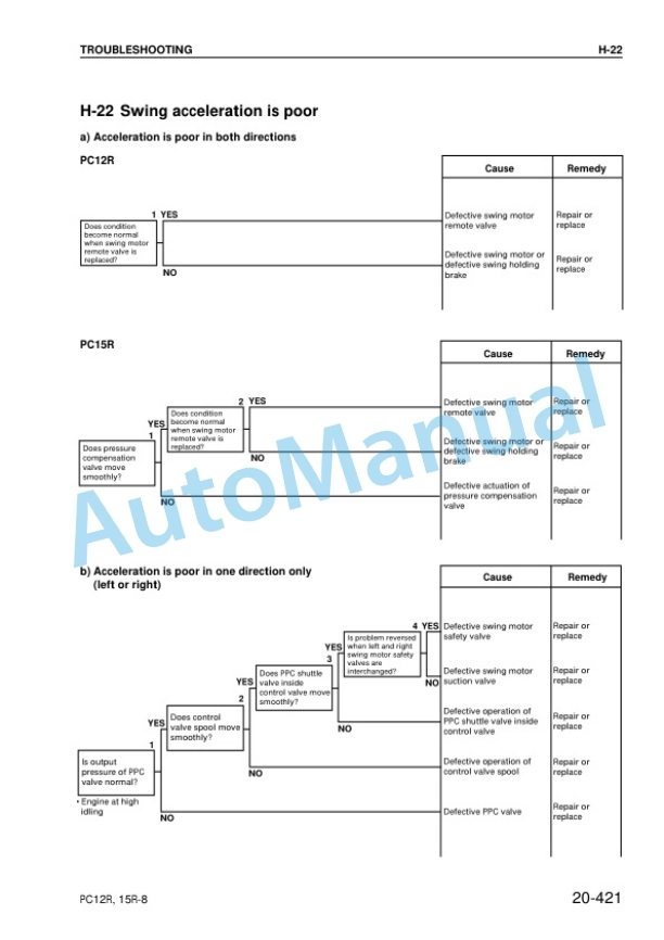
- 2.6.4.23. H22 Swing acceleration is poor
- 2.6.4.24. H23 Excessive overrun when stopping swing
- 2.6.4.25. H24 Excessive shock when stopping swing (in one direction only)
- 2.6.4.26. H25 Excessive abnormal noise when stopping swing
- 2.6.4.27. H26 Excessive hydraulic drift of swing
- 2.6.5. Troubleshooting of machine monitor system (M mode)
- 2.6.5.1. Electrical circuit diagram for M Mode related parts
- 2.6.5.2. M1 Abnormality in engine oil pressure caution lamp system
- 2.6.5.3. M2 Abnormality in charge caution lamp system
- 2.6.5.4. M3 Abnormality in engine water temperature caution lamp system
- 2.6.5.5. M4 Abnormality in preheating pilot lamp
- 2.6.5.6. M5 Abnormality in fuel gauge system
- 2.6.5.7. M6 Abnormality in service meter system
- 2.6.5.8. M7 Abnormality in night lighting system
- 3. DISASSEMBLY AND ASSEMBLY
- 3.1. Method of using manual
- 3.2. Precautions when carrying out operation
- 3.3. Special tool list
- 3.4. Starting motor
- 3.4.1. Removal and installation
- 3.5. Alternator
- 3.5.1. Removal and installation
- 3.6. Fuel injection pump
- 3.6.1. Removal and installation
- 3.7. Nozzle holder
- 3.7.1. Removal and installation
- 3.8. Water pump
- 3.8.1. Removal and installation
- 3.9. Thermostat
- 3.9.1. Removal and installation
- 3.10. Engine front seal
- 3.10.1. Removal and installation
- 3.11. Engine rear seal
- 3.12. Engine, hydraulic pump
- 3.12.1. Removal
- 3.12.2. Installation
- 3.13. Fuel tank
- 3.13.1. Removal and installation
- 3.14. Damper
- 3.14.1. Removal and installation
- 3.15. Center swivel joint
- 3.15.1. Removal and installation
- 3.15.2. Disassembly and assembly
- 3.16. Travel motor
- 3.16.1. Removal and installation
- 3.17. Sprocket
- 3.17.1. Removal and installation
- 3.18. Swing motor
- 3.18.1. Removal and installation
- 3.19. Revolving frame
- 3.19.1. Removal
- 3.19.2. Installation
- 3.20. Swing circle
- 3.20.1. Removal and installation
- 3.21. Idler
- 3.21.1. Removal and installation
- 3.21.2. Disassembly
- 3.21.3. Assembly
- 3.22. Idler cushion (rubber shoe)
- 3.22.1. Removal and installation
- 3.22.2. Disassembly and assembly
- 3.23. Idler cushion (steel shoe)
- 3.23.1. Disassembly
- 3.23.2. Assembly
- 3.24. Track roller
- 3.24.1. Removal and installation
- 3.24.2. Disassembly and assembly
- 3.25. Rubber shoe
- 3.25.1. Removal and installation
- 3.26. Steel shoe
- 3.26.1. Removal and installation
- 3.27. Hydraulic tank
- 3.27.1. Removal
- 3.27.2. Installation
- 3.28. Hydraulic oil cooler
- 3.28.1. Removal and installation
- 3.29. Hydraulic pump
- 3.29.1. Removal and installation
- 3.29.2. Removal and installation
- 3.30. Bucket cylinder
- 3.30.1. Removal and installation
- 3.31. Hydraulic cylinder
- 3.31.1. Removal and installation
- 3.31.2. Removal and installation
- 3.32. Canopy
- 3.32.1. Removal and installation
- 4. MAINTENANCE STANDARD
- 4.1. Swing circle
- 4.2. Track frame, recoil spring
- 4.3. Idler
- 4.4. Track roller
- 4.5. Track shoe
- 4.6. Hydraulic pump (PC15R8)
- 4.7. Control valve (PC12R8)
- 4.8. Control valve (PC15R8)
- 4.9. Center swivel joint
- 4.10. Swing motor
- 4.11. PPC valve
- 4.12. Hydraulic cylinder
- 4.13. Work equipment
- 5. OTHERS
- 5.1. Hydraulic circuit diagram PC12R8
- 5.2. Hydraulic circuit diagram PC15R8
- 5.3. Electric circuit diagram PC12R,15R8


There are no reviews yet.