
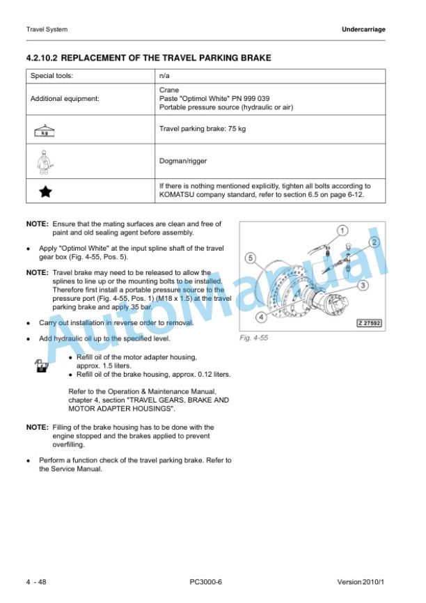
Description
-
Model List:
- PC3000-6 Hydraulic Mining Shovel
- 1. COVER
- 2. Foreword
- 2.1. Introduction
- 2.2. Safety Instructions
- 3. Specifications
- 3.1. Specifications PC3000
- 4. Structure, Function
- 4.1. INTRODUCTION
- 4.2. SAFETY
- 4.3. SPECIFICATIONS
- 4.4. MAIN ASSEMBLY GROUPS
- 4.4.1. General layout
- 4.4.2. Superstructure
- 4.4.3. Power House
- 4.4.4. Hydraulic Oil Reservoir
- 4.4.5. Hydraulic Oil Cooler
- 4.4.6. Fuel tank (Fuel reservoir)
- 4.4.7. Counter weight
- 4.4.8. Cab support
- 4.4.9. Operators cab
- 4.4.10. Control blocks
- 4.4.11. Swing gears
- 4.4.12. Under carriage
- 4.5. DRIVE
- 4.5.1. Prime drive assembly
- 4.5.2. Engine and gearbox mount
- 4.5.3. Torque supports
- 4.5.4. Radiator fan Drive Assy.
- 4.5.5. Pump distributor gearbox (PTO)
- 4.5.6. Coupling
- 4.5.7. Air cleaner
- 4.6. HYDRAULIC OIL RESERVOIR
- 4.6.1. Hydraulic oil reservoir
- 4.6.2. Return and leak oil filter
- 4.6.3. Breather Filter
- 4.6.4. Location of electrical components
- 4.6.5. Transfer Pump, hydraulic service
- 4.7. HYDRAULIC OIL COOLING
- 4.7.1. General
- 4.7.2. Hydraulic oil cooling circuit
- 4.7.3. Back pressure valve adjustment
- 4.7.4. Fan drive
- 4.7.5. Cooler fan drive adjustment
- 4.8. CONTROLLING
- 4.8.1. Pilot pressure supply and adjustment
- 4.8.2. Slew brakes
- 4.8.3. Travel parking brake
- 4.8.4. Check of the pilot control logic
- 4.9. COMPONENTS
- 4.9.1. Main control block and valve arrangement
- 4.9.2. Distributor manifold
- 4.9.3. Main control block
- 4.9.4. Compact valve blocks
- 4.9.5. Compact valve blocks
- 4.9.6. Auxiliary gear pumps
- 4.9.7. Hydraulic cylinder
- 4.9.8. Swing ring
- 4.10. MAIN HYDRAULIC PUMPS AND PUMP REGULATION
- 4.10.1. General
- 4.10.2. Main pump operating principles
- 4.10.3. Main pump checks and adjustments
- 4.10.4. Electronic pump regulation
- 4.10.5. Pump Controller CR700
- 4.10.6. Multi Monitor
- 4.10.7. Multimonitor software instruction
- 4.10.8. Trouble shooting pump and pump regulation
- 4.11. OPERATING HYDRAULIC
- 4.11.1. General layout
- 4.11.2. Floating function of boom and stick only FSA
- 4.11.3. Check and Adjustments for MRVs and SRVs
- 4.11.4. Hydraulic for the swing circuit
- 4.11.5. Travel circuit
- 4.12. TRACK TENSION SYSTEM
- 4.12.1. General layout
- 4.12.2. Track tensioning function
- 4.12.3. Track tensioning adjustment
- 4.13. ACCESS LADDER HYDRAULICALLY OPERATED
- 4.13.1. Access ladder
- 4.13.2. Access ladder functional description
- 4.14. CENTRAL REFILLING SYSTEM
- 4.14.1. Functional description
- 4.15. HINTS FOR READING THE HYDRAULIC CIRCUIT DIAGRAM
- 4.15.1. General
- 4.15.2. Symbolic
- 4.16. HINTS FOR READING THE ELECTRIC CIRCUIT DIAGRAM
- 4.16.1. Designation of electrical components
- 4.16.2. Electric symbols
- 4.16.3. Symbols
- 4.17. ELECTRONIC TEXT MONITORING SYSTEM ETM
- 4.17.1. General Function
- 4.18. AUTOMATIC LUBRICATION SYSTEM
- 4.18.1. General Function
- 4.18.2. Function of a lubrication cycle
- 4.18.3. Lubrication pump drive
- 4.18.4. Lubrication pump
- 4.18.5. Lubricant Injector (metering valve)
- 4.18.6. End line pressure switch
- 4.18.7. Lubricant in line filter
- 4.18.8. Lubricant level sensor
- 4.18.9. Lubrication system function and controlling
- 4.18.10. Adjustment of the lubrication system with ETM
- 4.18.11. Trouble shooting lubricating system
- 5. Troubleshooting
- 5.1. Table of Contents
- 5.2. Introduction
- 5.2.1. Safety Notes
- 5.2.2. Description of this Troubleshooting Manual
- 5.2.3. General Precautions
- 5.3. Electrical Parts
- 5.3.1. Componant Locations
- 5.3.2. Engine Electrical Parts
- 5.3.3. Electrical Parts On PTO, etc
- 5.3.4. Electrical Parts on Pilot Control Frame
- 5.3.5. Electrical Parts on Main Hydraulic Reservoir
- 5.3.6. Electrical Parts on Switch Board X2
- 5.3.7. Electrical Parts on Hydraulic Ldder
- 5.3.8. Electrical Parts of Automatic Lube System
- 5.3.9. Electrical Parts on Air Cleaner and Fuel Tank
- 5.3.10. Overview Connector Types
- 5.3.11. Standard Value Table for Electrical Componants
- 5.3.12. PT100 Temperature Charts
- 5.4. Troubleshooting by Trouble Code
- 5.4.1. Message 1 Gear Lubrication out of Function (PTO)
- 5.4.2. Message 2 Engine Air Filter Restricted
- 5.4.3. Message 3 Filter for Control Oil Restricted
- 5.4.4. Message 4 Oil Tank Breather Filter Restricted
- 5.4.5. Message 5 Return Oil Filter Restricted
- 5.4.6. Message 6 Leak Oil Filter Restricted
- 5.4.7. Message 7 Hydraulic Oil Temperature Too High
- 5.4.8. Message 9 Low Idle Too High Coolant Temperature
- 5.4.9. Message 10 Engine Shutdown Too Low Engine Oil Temperature
- 5.4.10. Message 14 Too Low Hydraulic Oil Level
- 5.4.11. Message 15 Caution, Slew Gear House Brake On
- 5.4.12. Message 16 Caution, Travel Gear House Brake On
- 5.4.13. Message 17 No Clearance For Starting, Shift Engine to Low Idle
- 5.4.14. Message 18 Central Lube System Fault
- 5.4.15. Message 19 Slew Ring Gear Lubrication Fault
- 5.4.16. Message 20 Pilot Control CutOut
- 5.4.17. Message 21 Central Lube System Empty Grease Barrel
- 5.4.18. Message 22 Central Lube System Empty Grease Barre
- 5.4.19. Message 24 Engine Problem Stop All Control
- 5.4.20. Message 32 PTO Gear Lube Filter Restricted
- 5.4.21. Message 33 Cooler Fan Drive Filter Restricted
- 5.4.22. Message 39 Engine Shutdown . Main ShutOff (Gate) Volve
- 5.4.23. Message 42 Too Low Coolant Pressure
- 5.4.24. Message 43 Engine Shutdown Emergency Stop Switch Actuated
- 5.4.25. Message 44 Engine Shutdown Safety Switch Actuated
- 5.4.26. Message 45 Warning Signal from Engine Control Module
- 5.4.27. Message 48 Too High PTO Gear Oil Temperature.
- 5.4.28. Message 50 Caution, Pull Switch From Ground Man Actuated
- 5.4.29. Message 51 Engine Shutdown Pull Switch From Ground Man Actuated
- 5.4.30. Message 52 Load Limit Clam Defective
- 5.4.31. Message 53 Pressure Switch of CLS Actuated
- 5.4.32. Message 55 Refill Hyrdaulic Oil
- 5.4.33. Message 57 Load Limit Regulation Fault
- 5.4.34. Message 58 Strainer Oil Cooler Restricted
- 5.4.35. Message 59 CLS Refill Grease Container
- 5.4.36. Message 60 SLS Refill Grease Barrel
- 5.5. Troubleshooting by Symptoms
- 5.5.1. Symptoms of the Hydraulic System
- 6. Disassembly and Assembly
- 6.1. INTRODUCTION
- 6.1.1. Contents of the binder
- 6.1.2. Foreword
- 6.2. SAFETY
- 6.3. SUPERSTRUCTURE
- 6.3.1. Superstructure overview
- 6.3.2. Engine House
- 6.3.3. Diesel Engine
- 6.3.4. Torsion Coupling
- 6.3.6. Hydraulics
- 6.3.7. Slew Drive
- 6.3.8. Lubrication Pumps
- 6.3.9. Operaotors Cab
- 6.3.10. Cab Base
- 6.3.11. Access Ladder
- 6.3.12. Counterweight
- 6.3.13. Superstructure Lifting
- 6.3.14. Fuel Tank
- 6.4. UNDERCARRIAGE
- 6.4.1. Undercarriage Overview
- 6.4.2. Travel System
- 6.4.3. Car Body
- 6.5. ATTACHMENT
- 6.5.1. Face Shovel
- 6.5.2. Backhoe
- 6.5.3. Metering Valves
- 6.5.4. Cylinder Bypass Test
- 6.6. SERVICE INFORMATION
- 6.6.1. Fuel and Lubricants
- 6.6.2. Filling capacities
- 6.6.3. Work Instructions
- 6.6.4. Weight Tables
- 6.6.5. Torque Charts
- 6.6.6. Blind Plugs
- 6.6.7. Conversion Table
- 6.6.8. Tools
- 6.7. TOOLS CATALOGUE






There are no reviews yet.