
Description
-
Model List:
- PC5500-6 Diesel Hydraulic Excavator
- 1. PC55006D Service Manual
- 1.1. Contents and Foreword
- 1.2. Main Assembly Groups
- 1.3. Drive
- 1.4. Hydraulic Oil Reservoir
- 1.5. Hydraulic Oil Cooling
- 1.6. Controlling
- 1.7. Components
- 1.8. Main Hydraulic Pumps and Pump Regulation
- 1.9. Operating Hydraulics
- 1.10. ydraulics for the Attachment Cylinders
- 1.11. Hydraulics for the Swing Circuit
- 1.12. ydraulics for the Travel Circuit
- 1.13. Hydraulic Track Tensioning System
- 1.14. Access Ladder
- 1.15. Refilling Arm
- 1.16. Hints for Reading Hydraulic Circuit Diagram
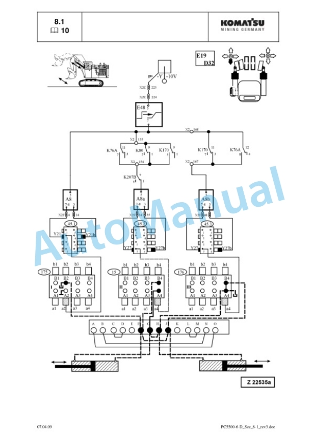
- 1.17. Hints for Reading Electric Circuit Diagram
- 1.19. Lubrication System
- 2. PC55006D Disassembly and Assembly
- 2.1. Introduction
- 2.1.1. Contents of the binder
- 2.1.2. Foreword
- 2.1.2.1. Service
- 2.2. Safety
- 2.2.1. Safety Instructions
- 2.2.1.1. Method of using this manual
- 2.2.1.2. General precautions
- 2.2.1.3. Preparations for work
- 2.2.1.4. Precautions during work
- 2.2.1.5. Warning of special dangers
- 2.2.1.6. Special safety equipment
- 2.2.2. Lifting gears
- 2.2.2.1. Wire ropes
- 2.2.2.2. Sling accessory
- 2.2.2.3. Weight tables
- 2.2.3. Torque charts according to DIN
- 2.2.3.1. Metric standard thread
- 2.2.3.2. Metric fine thread
- 2.2.3.3. Cummins motor torques metric
- 2.2.3.4. Cummins motor torques U.S. customary
- 2.2.3.5. SAE flange connections
- 2.2.4. Blind plugs
- 2.2.4.1. Dummy plates for SAE flanches
- 2.2.4.2. Classification of threads to the nominal width
- 2.2.4.3. Plugs and fittings according to DIN 2353
- 2.2.5. Conversation table
- 2.2.5.1. Method of using the conversation table
- 2.2.5.2. Millimeter Inch Kilogram Pound
- 2.2.5.3. Liter U.S. Gallon Liter U.K. Gallon
- 2.2.5.4. KGm ft.lb
- 2.2.5.5. Bar PSI / PSI Bar
- 2.2.5.6. Basic Values in Ohm according to DIN 43 76
- 2.2.5.7. Temperature
- 2.2.6. Explanation of abbreviations
- 2.3. Superstructure
- 2.3.1. Diesel engine
- 2.3.1.1. Removal of the diesel engines
- 2.3.1.2. Engine torque support and engine/PTO mounts
- 2.3.1.3. Alternator
- 2.3.1.4. Batteries
- 2.3.1.5. Radiator fan
- 2.3.1.6. Radiators
- 2.3.1.7. Starter system
- 2.3.1.8. Torsion type coupling (GEISLINGER)
- 2.3.2.1. Main pumps
- 2.3.2.2. PTO oil pump (auxiliary pump)
- 2.3.2.3. Oil Circulation pump (auxiliary pump)
- 2.3.2.4. Pump distributor gearbox (PTO)
- 2.3.3. Hydraulics
- 2.3.3.1. Hydraulic cooler fan drive pump
- 2.3.3.2. Hydraulic cooler fan assembly
- 2.3.3.3. Hydraulic oil coolers
- 2.3.3.4. Main relief valves (MRV)
- 2.3.3.5. Pilot oil pump (gear pump)
- 2.3.3.6. Main gate valve
- 2.3.3.7. Hydraulic oil reservoir
- 2.3.3.8. Main control valve blocks
- 2.3.3.9. Service line relief valves (SRV)
- 2.3.3.10. Anticavitation valves (ACV)
- 2.3.3.11. Replacement of the ACV on manifold
- 2.3.3.12. Throttle check valves
- 2.3.3.13. Manifold
- 2.3.4. Slew drive
- 2.3.4.1. Slew gear
- 2.3.4.2. Swing motor
- 2.3.4.3. Slew parking brake
- 2.3.4.4. Dynamic slew brake
- 2.3.4.5. Swing circle lubrication pinion (dummy wheel)
- 2.3.5. Lubrication pumps
- 2.3.5.1. Removal of the lubrication pump
- 2.3.5.2. Replacement of the lubricating pump
- 2.3.6. Pump controller MC7
- 2.3.6.1. Removal of the pump controller MC7
- 2.3.6.2. Replacement of the pump controller MC7
- 2.3.7. Operators cab
- 2.3.7.1. Removal of the operators cab
- 2.3.7.2. Replacement of the operators cab
- 2.3.7.3. Cabmounts
- 2.3.7.4. Front window
- 2.3.7.5. Operators seat
- 2.3.7.7. Access ladder
- 2.3.7.8. Removal of the cab base
- 2.3.7.9. Replacement of the cab base
- 2.3.8. Counterweight
- 2.3.8.1. Removal of the counterweight
- 2.3.8.2. Replacement of the counterweight
- 2.3.9. Superstructure lifting
- 2.3.9.1. Remove the superstructure from the undercarriage
- 2.3.9.2. Install the superstructure onto the undercarriage
- 2.3.10. Fuel tank
- 2.3.10.1. Removal of the fuel tank
- 2.3.10.2. Replacement of the fuel tank
- 2.4. Undercarriage
- 2.4.1. Travel system
- 2.4.1.1. Track group
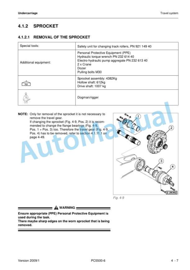
- 2.4.1.2. Sprocket
- 2.4.1.3. Guide wheels
- 2.4.1.4. Track tensioning accumulators
- 2.4.1.5. Track tension valve block
- 2.4.1.6. Hydraulic hoses of the track tensioning system
- 2.4.1.7. Travel brake valve block (overspeed valve)
- 2.4.1.8. Track tensioning cylinders
- 2.4.1.9. Travel motor
- 2.4.1.10. travel parking brake
- 2.4.1.11. Travel gearbox
- 2.4.1.12. Carrier roller
- 2.4.1.13. Track roller
- 2.4.2. Car body
- 2.4.2.1. Removal of the car body (type with mounting pins)
- 2.4.2.2. Replacement of the car body (type with mounting pins)
- 2.4.2.3. Removal of the car body (type with bolted connection)
- 2.4.2.4. Replacement of the car body (type with bolted connection)
- 2.4.2.5. Rotary joint
- 2.4.2.6. swing circle
- 2.5. Attachment
- 2.5.1. Backhoe
- 2.5.1.1. Boom
- 2.5.1.2. Stick
- 2.5.1.3. Bucket
- 2.5.1.4. Bucket link rod and steering rods
- 2.5.1.5. Ground engaging tools (GET)
- 2.5.1.6. Hydraulic hoses at the backhoe attachment
- 2.5.2. Face shovel
- 2.5.2.1. Boom
- 2.5.2.2. Stick
- 2.5.2.3. Bull clam bucket
- 2.5.2.4. Ground engaging tools (GET)
- 2.5.2.5. Hydraulic hoses at the face shovel attachment
- 2.5.3. Metering Valves (grease Injectors) at the attachment
- 2.5.3.1. Removal of the metering valves (grease injectors)
- 2.5.3.2. Replacement of the metering valves (grease injectors)
- 2.5.4. Cylinder bypass test
- 2.6. Appendix
- 2.6.1. Fluids and lubricants
- 2.6.1.1. Lubricants for operation in moderate and hot climates
- 2.6.1.2. Lubricants for operation in cold and arctic climates
- 2.6.2. Filling capacities
- 2.6.3. Tools list
- 2.6.3.1. Used special tools (overview)
- 2.6.3.2. KOMATSU tools catalogue
- 2.6.4. Work Instructions
- 2.6.4.1. Surface coating with INTERZINC 697
- 2.6.4.2. Remove / install the crawler carrier
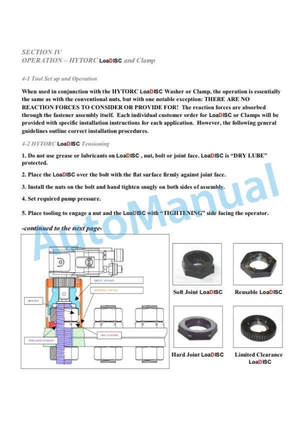
- 2.6.4.3. Use of the hydraulic torque wrench (suppliers documentation)
- 2.6.4.4. Repair manual TRAVEL GEAR (in extracts)
- 2.6.5. PARTS SERVICE NEWS
- 2.6.5.1. AH03506b
- 2.6.5.2. AH03509a
- 2.6.5.3. AH03510
- 2.6.5.4. AH03511
- 2.6.5.5. AH03512
- 2.6.5.6. AH04518
- 2.6.5.7. AH05501a
- 2.6.5.8. AH05510
- 2.6.5.9. AH05511
- 2.6.5.10. AH05520a
- 2.6.5.11. AH05525
- 2.6.5.12. AH05535c
- 2.6.5.13. AH06543a
- 2.6.5.14. AH07509
- 2.6.5.15. AH07526
- 2.6.5.16. AH08503
- 2.6.5.17. AH08507


There are no reviews yet.