
Description
-
Model List:
- PC7000-6 Hydraulic Mining Shovel
- 1. SHOP MANUAL Cover
- 2. FOREWORD SAFETY
- 2.1. Foreword
- 2.1.1. Before reading this manual
- 2.1.2. Contents of this binder
- 2.1.3. Division of the binder
- 2.2. SAFETY
- 2.2.1. SAFETY INFORMATION
- 2.2.2. OVERVIEW
- 2.2.3. SOUND PRESSURE AND VIBRATION LEVELs IN THE OPERATORS CAB.
- 2.2.4. GENERAL PRECAUTIONS COMMON TO OPERATION ON THE EXCAVATOR
- 2.2.5. PRECAUTION FOR MAINTENANCE
- 2.2.6. ADDITIONAL SAFETY INFORMATION FOR TROUBLESHOOTING AND ADJUSTMENTS
- 2.2.7. SPECIAL SAFETY EQUIPMENT
- 3. SPECIFICATION
- 3.1. PC70006
- 4. STRUCTURE FUNCTION
- 4.2. Introduction
- 4.2.1. Foreword
- 4.2.2. Recommendations for environmentally friendly operation and maintenance of hydraulic mining shovels
- 4.2.3. Explanation of abbreviations
- 4.2.4. Diagrams and illustrations in this manual
- 4.3. Specifications
- 4.3.1. Lifting Gears
- 4.3.2. Safety hints for sling accessory
- 4.3.3. Standard Tightening Torque Chart
- 4.3.4. Conversion Table
- 4.3.5. Blind plugs
- 4.3.6. Classification of threads to the nominal width
- 4.3.7. Plugs and fittings according to ISO 84341 / DIN 2353
- 4.4. Main assembly groups
- 4.4.1. General layout
- 4.4.2. Superstructure
- 4.4.3. Machine house
- 4.4.4. Hydraulic oil tank
- 4.4.5. Hydraulic oil cooler
- 4.4.6. Fuel tank
- 4.4.7. Cab support
- 4.4.8. Operators cab
- 4.4.9. Main control blocks (FSA)
- 4.4.10. Slew gear
- 4.4.11. Undercarriage
- 4.4.12. Slew ring
- 4.4.13. Attachment
- 4.5. Drive
- 4.5.1. Prime drive assembly
- 4.5.2. Engine and PTO mounts
- 4.5.3. Flexible coupling
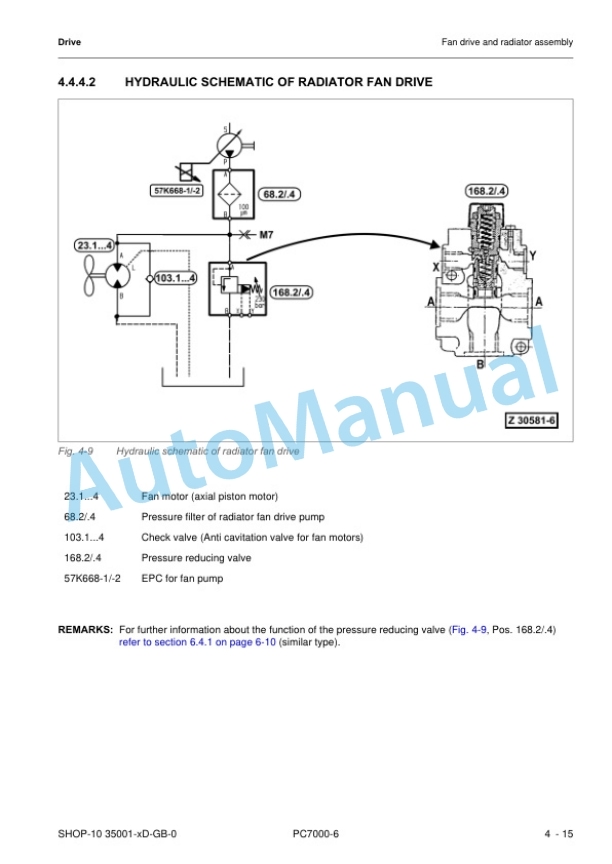
- 4.5.4. Fan drive and radiator assembly
- 4.5.5. Pump distributor gearbox (PTO)
- 4.5.6. Hydraulic pumps location, drive speed and flow rates
- 4.5.7. Air cleaner
- 4.6. Hydraulic oil tank
- 4.6.1. General layout
- 4.6.2. Hydraulic oil tank, location of the electric equipment
- 4.6.3. Suction oil tank with strainers
- 4.6.4. Return oil collector pipe with strainer
- 4.6.5. Back pressure valve
- 4.6.6. Transfer pump
- 4.6.7. Return and leak oil filter
- 4.6.8. Breather filter
- 4.7. Hydraulic oil cooling
- 4.7.1. Overall view of the hydraulic oil cooling
- 4.7.2. Function of the hydraulic oil cooling circuit
- 4.7.3. Adjustment of the back pressure valve
- 4.7.4. Stepless cooler fan RPM control
- 4.7.5. Oil cooler fan speed testing/adjustment
- 4.8. Controlling
- 4.8.1. General layout
- 4.8.2. Control and filter panels location of components
- 4.8.3. Pilot pressure supply and adjustments
- 4.8.4. Function of the electro hydraulic control system
- 4.8.5. Hand lever (joystick) control
- 4.8.6. Foot pedal control
- 4.8.7. Hand lever foot pedal monitoring
- 4.8.8. Valve solenoid adjustment
- 4.8.9. ACCEL DECEL time adjustment
- 4.9. Components
- 4.9.1. Main control blocks and high pressure screens (FSA)
- 4.9.2. Main control blocks with valves (FSA)
- 4.9.3. Main control blocks with valves (BHA)
- 4.9.4. Distributor manifold location of restrictor blocks and anti cavitation valves (FSA)
- 4.9.5. Distributor manifold location of restrictor blocks and anti cavitation valves (BHA)
- 4.9.6. Restrictor block with secondary relief valve
- 4.9.7. Anticavitation valve (ACV) block
- 4.9.8. Remote control valves
- 4.9.9. Directional solenoid valves
- 4.9.10. Proportional solenoid valves
- 4.9.11. Highpressure screen
- 4.9.12. Control blocks and valves
- 4.9.13. Travel brake valve
- 4.9.14. Pressure reducing valve
- 4.9.15. Directional valves
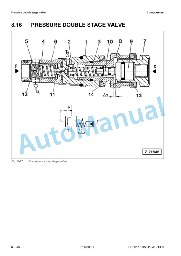
- 4.9.16. Pressure double stage valve
- 4.9.17. Hydraulic cylinder
- 4.10. Main hydraulic pumps, pump regulation, valve control monitoring system
- 4.10.1. General
- 4.10.2. Main pumps
- 4.10.3. Electronic pump regulation system
- 4.10.4. Pump valve controllers
- 4.10.5. Multimonitor
- 4.10.6. Service menu 01 Monitoring
- 4.10.7. Using Multimonitor functions for monitoring
- 4.10.8. Service menu 02 Abnormality Record
- 4.10.9. Service menu 03 Default
- 4.10.10. Service menu 04 Adjustment
- 4.10.11. Service menu 05 Display Setup
- 4.10.12. Checks and adjustments
- 4.10.13. Engine speed sensors (pickup)
- 4.11. Operating hydraulics
- 4.11.1. General
- 4.11.2. Spool functions (FSA)
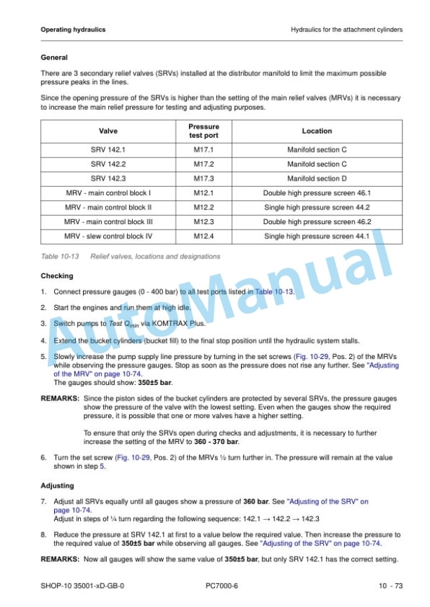
- 4.11.3. Hydraulics for the attachment cylinders
- 4.11.4. Hydraulics for the slew circuit
- 4.11.5. Hydraulics for the travel circuit
- 4.12. Hydraulic track tensioning system
- 4.12.1. General
- 4.12.2. Functional description
- 4.12.3. Double stage valve
- 4.12.4. Tensioning cylinder
- 4.12.5. Adjustments / checks
- 4.13. Access ladder, hydraulically operated
- 4.13.1. Overview
- 4.13.2. Function of the hydraulically operated access ladder
- 4.13.3. Adjustments / checks
- 4.14. Central refilling system (Service arm)
- 4.14.1. Refilling arm location
- 4.14.2. Function
- 4.15. Hints for reading the hydraulic diagram
- 4.15.1. General
- 4.15.2. Hydraulic symbols
- 4.16. Hints for reading the electric wiring diagram
- 4.16.1. General
- 4.16.2. Reference code of the electrical components
- 4.16.3. Graphical symbols
- 4.16.4. Drawing concept
- 4.16.5. Cable marking
- 4.17. KOMTRAX Plus MTC control system
- 4.17.1. General
- 4.17.2. Specifications for operators
- 4.17.3. Tables of all provided messages
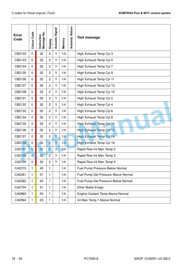
- 4.17.4. Ccodes for Diesel engines (Tier2)
- 4.17.5. Flow charts (14) of KOMTRAX Plus main screens
- 4.17.6. KOMTRAX Plus service level
- 4.17.7. InterfaceConnection KOMTRAX Plus controller MTC
- 4.17.8. segment error code indication
- 4.17.9. Wiring of the KOMTRAX Plus controller
- 4.17.10. MTC control system global layout
- 4.17.11. Global layout of the internal CAN BUS
- 4.17.12. The nodes in the CAN BUS system
- 4.18. Lubrication system
- 4.18.1. General overview SLS CLS1/2
- 4.18.2. Basic function of the lubrication systems
- 4.18.3. Lubrication systems (SLS CLS1/2)
- 4.18.4. Lubrication cycle
- 4.18.5. Hydraulically driven lube pump
- 4.18.6. Lubricant injectors
- 4.18.7. Vent valve and grease outlet filter
- 4.18.8. Endline switch
- 4.18.9. Lubricant level sensors
- 4.18.10. Commissioning
- 4.19. Deep temperature equipment (option)
- 4.19.1. General information
- 4.19.2. Preheating procedure
- 4.19.3. Constant heating of travel motors (TTT equipment below40C only)
- 4.19.4. Component location
- 4.19.5. Components of TT equipment









There are no reviews yet.