
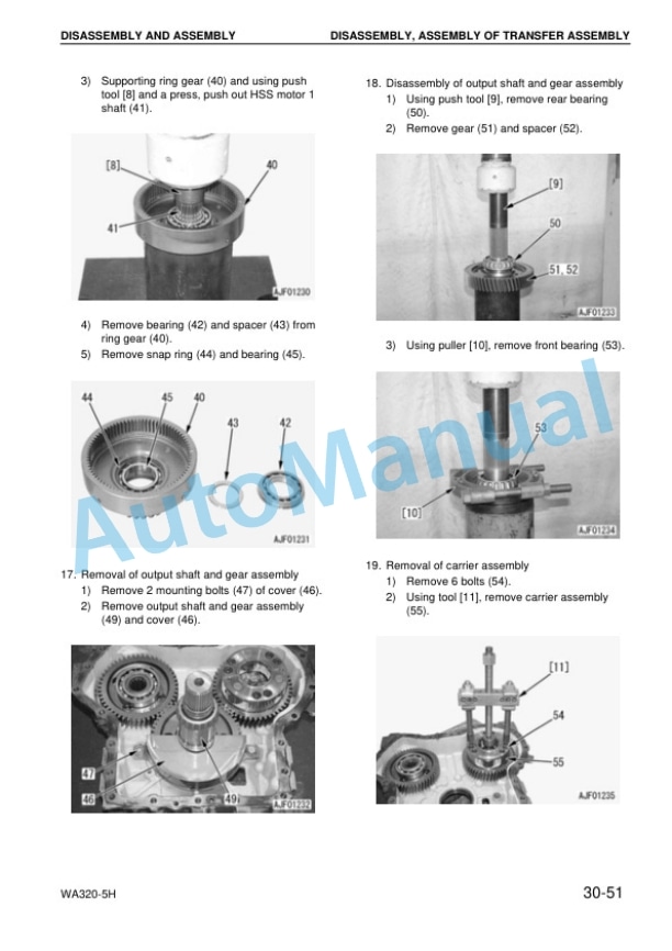
Description
-
Model List:
- WA320-5H Wheel Loader
- 1. SAFETY
- 1.1. SAFETY NOTICE
- 2. FOREWORD
- 2.1. GENERAL
- 2.2. HOW TO READ THE SHOP MANUAL
- 2.3. HOISTING INSTRUCTIONS
- 2.4. METHOD OF DISASSEMBLING, CONNECTING PUSHPULL TYPE COUPLER
- 2.5. COATING MATERIALS
- 2.6. STANDARD TIGHTENING TORQUE
- 2.7. ELECTRIC WIRE CODE
- 2.8. CONVERSION TABLE
- 2.9. UNITS
- 3. GENERAL
- 3.1. GENERAL ASSEMBLY DRAWINGS
- 3.2. SPECIFICATIONS
- 3.3. WEIGHT TABLE
- 3.4. PROPER SELECTION OF FUEL, COOLANT AND LUBRICANTS
- 4. STRUCTURE, FUNCTION AND MAINTENANCE STANDARD
- 4.1. Engine mount and transfer mount
- 4.2. Power train system diagram
- 4.3. Drive shaft (propeller shaft)
- 4.4. HST hydraulic piping diagram
- 4.5. Highpressure relief valve
- 4.6. Lowpressure relief valve
- 4.7. HST charge pump
- 4.8. Speedrelated valve (DA valve)
- 4.9. Highpressure cutoff valve
- 4.10. Forwardreverse shuttle valve
- 4.11. Transfer
- 4.12. Clutch solenoid valve
- 4.13. Axle
- 4.14. Differential
- 4.15. Limitedslip differential
- 4.16. Final drive
- 4.17. Axle mounting and center hinge pin
- 4.18. Steering piping
- 4.19. Steering column
- 4.20. Priority valve
- 4.21. Orbitroll valve
- 4.22. Cushion valve
- 4.23. Steering cylinder
- 4.24. Emergency steering piping
- 4.25. Emergency steering valve
- 4.26. Brake piping
- 4.27. Brake valve
- 4.28. Accumulator (for brake)
- 4.29. Slack adjuster
- 4.30. Brake
- 4.31. Parking brake control
- 4.32. Parking brake
- 4.33. Hydraulic piping
- 4.34. Work equipment lever linkage
- 4.35. Hydraulic tank
- 4.36. gear pump unit
- 4.37. Accumulator (for PPC circuit)
- 4.38. Lock valve
- 4.39. valve
- 4.40. Accumulator (forE.C.S.S.)
- 4.41. Hydraulic piping of cooling system
- 4.42. Cooling fan motor
- 4.43. Work equipment control valve
- 4.44. Work equipment PPC valve
- 4.45. Attachment PPC valve
- 4.46. Work equipment linkage
- 4.47. Bucket
- 4.48. Bucket positioner and boom kickout
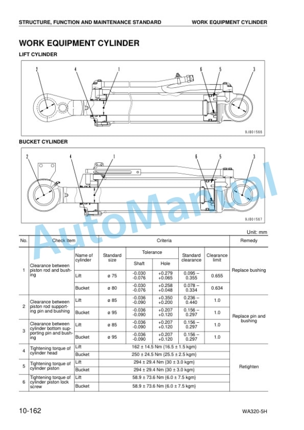
- 4.49. Work equipment cylinder
- 4.50. Air conditioner
- 4.51. Machine monitoring system
- 4.52. Machine monitor
- 4.53. List of items displayed on monitor
- 4.54. Electrical system (HST controller system)
- 4.55. HST controller
- 4.56. Function of selecting directional selector switch
- 4.57. Engine start circuit
- 4.58. Engine stop circuit
- 4.59. Preheating circuit (automatic preheating system)
- 4.60. Parking brake circuit
- 4.61. Electronically controlled suspension system
- 4.62. Sensors
- 4.63. STANDARD VALUE TABLE FOR engine
- 4.64. STANDARD VALUE TABLE FOR CHASSIS
- 5. TESTING AND ADJUSTING
- 5.1. Tools for testing, adjusting, and troubleshooting
- 5.2. Measuring engine speed
- 5.3. Measuring exhaust gas color
- 5.4. Adjusting valve clearance
- 5.5. Measuring compression pressure
- 5.6. Measuring blowby pressure
- 5.7. Testing and adjusting fuel injection timing
- 5.8. Measuring engine oil pressure
- 5.9. Measuring, testing operating force of accelerator pedal
- 5.10. Adjusting engine stop solenoid
- 5.11. Adjusting engine speed sensor
- 5.12. Testing and adjusting air conditioner compressor belt tension
- 5.13. Measuring directional lever
- 5.14. Testing and adjusting HST oil pressure
- 5.15. Measuring clutch control pressure
- 5.16. Testing and adjusting steering wheel
- 5.17. Testing and adjusting steering oil pressure
- 5.18. Bleeding air from steering circuit
- 5.19. Testing hydraulic fan
- 5.20. Measuring brake pedal
- 5.21. Testing and adjusting brake pedal linkage
- 5.22. Measuring brake oil pressure
- 5.23. Bleeding air from brake circuit
- 5.24. Measuring parking brake performance
- 5.25. Measuring and adjusting work equipment control lever
- 5.26. Testing and adjusting work equipment hydraulic pressure
- 5.27. Testing and adjusting work equipment PPC oil pressure
- 5.28. Bleeding air
- 5.29. Releasing remaining pressure in hydraulic circuit
- 5.30. Testing and adjusting bucket positioner
- 5.31. Testing and adjusting of boom kickout
- 5.32. Checking proximity switch actuation display lamp
- 5.33. Special functions of machine monitor
- 5.34. Pm CLINIC INSPECTION CHART
- 5.35. TESTING AND ADJUSTING
- 5.36. Points to remember when troubleshooting
- 5.37. Sequence of events in troubleshooting
- 5.38. Precautions when carrying out maintenance
- 5.39. Check before troubleshooting
- 5.40. Categories, procedure, and method of using troubleshooting charts
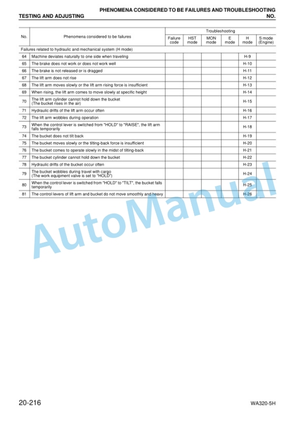
- 5.41. Phenomena considered to be failures and troubleshooting no.
- 5.42. Connection table for connector pin numbers
- 5.43. Tadapter table
- 5.44. Connector types and mounting locat
- 5.45. ions
- 5.46. Connector layout drawing
- 5.47. TROUBLESHOOTING
- 5.48. Before troubleshooting code display
- 5.49. Before troubleshooting electrical system
- 5.50. Information contained in troubuleshooting table
- 5.51. TROUBLESHOOTING OF HST CONTROLLER SYSTEM (HST MODE)
- 5.52. Before troubleshooting code display
- 5.53. Before troubleshooting electrical system
- 5.54. Information contained in troubuleshooting table
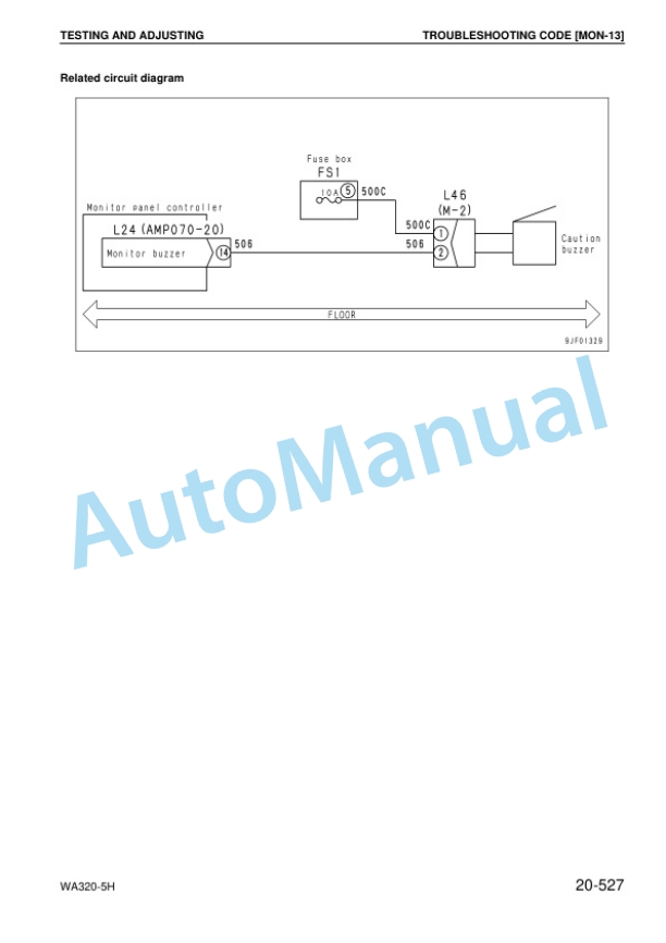
- 5.55. TROUBLESHOOTING OF monitor SYSTEM (mon MODE)
- 5.56. Before troubleshooting electrical system
- 5.57. Information contained in troubuleshooting table
- 5.58. TROUBLESHOOTING OF ELECTRICAL SYSTEM (E MODE)
- 5.59. Method of using troubleshooting chart
- 5.60. Failure code and cause table
- 5.61. TROUBLESHOOTING OF HYDRAULIC, MECHANICAL SYSTEM (H MODE)
- 5.62. Method of using troubleshooting charts
- 5.63. TROUBLESHOOTING OF ENGINE (S MODE)
- 5.64. How to read this manual
- 5.65. Precautions when carrying out operation
- 5.66. Special tool list
- 5.67. Sketch of special tools
- 5.68. Removal, installation of fuel injection pump assembly
- 5.69. Removal, installation of nozzle holder assembly
- 5.70. Removal, installation of cylinder head assembly
- 5.71. Removal, installation of engine assembly
- 5.72. Removal, installation of radiator assembly
- 5.73. Removal, installation of air aftercooler
- 5.74. Removal, installation of hydraulic oil cooler assembly
- 5.75. Removal, installation of cooling fan and fan motor assembly
- 5.76. Removal, installation of fuel tank assembly
- 5.77. Removal, installation of transfer
- 5.78. Disassembly, assembly of transfer assembly
- 5.79. Removal, installation of parking brake assembly
- 5.80. Disassembly, assembly of parking brake assembly
- 5.81. Removal, installation of front axle assembly
- 5.82. Removal, installation of rear axle assembly
- 5.83. Disassembly, assembly of axle housing assembly
- 5.84. Disassembly, assembly of differential assembly
- 5.85. Removal, installation of HST pump and 4gear pump assembly
- 5.86. Removal, installation of HST motor 1 assembly
- 5.87. Removal, installation of HST motor 2 assembly
- 5.88. Removal, installation of work equipment control valve assembly
- 5.89. Removal, installation of travel damper valve assembly
- 5.90. Removal, installation of hydraulic tank assembly
- 5.91. Removal, installation of work equipment assembly
- 5.92. Disassembly and assembly of HST pump assembly
- 5.93. Disassembly and assembly of HST motor assembly
- 5.94. Disassembly, assembly of hydraulic cylinder assembly
- 5.95. Removal, installation of operators cab assembly
- 5.96. Removal, installation of operators cab glass (Stuckglass)
- 5.97. Removal, installation of center hinge pin
- 5.98. Removal, installation of counterweight
- 5.99. Removal, installation of air conditioner unit assembly
- 5.100. Removal, installation of air conditioner compressor assembly
- 5.101. Removal, installation of monitor panel
- 6. DISASSEMBLY AND ASSEMBLY
- 7. OTHERS




There are no reviews yet.