
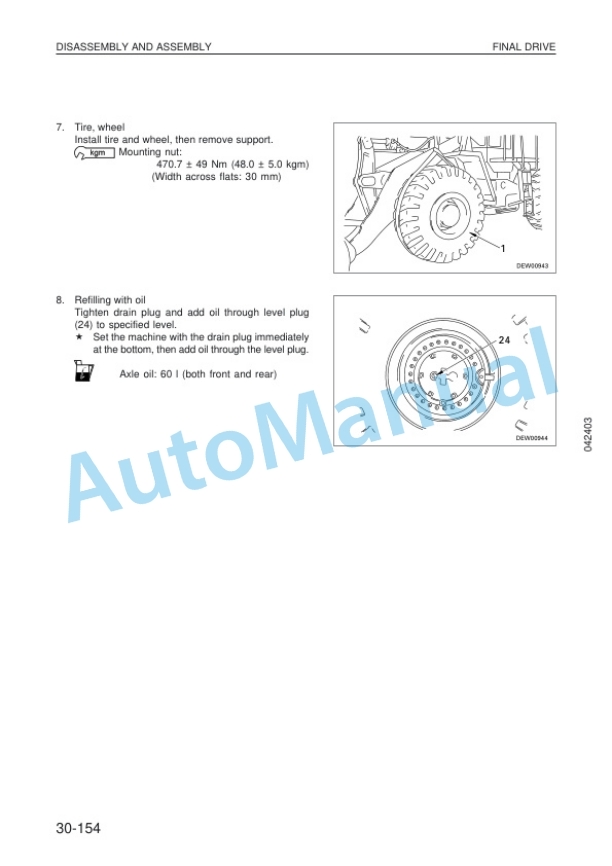
Description
-
Model List:
- WA420-3 Wheel Loader
- 1. COVER
- 2. Contents
- 3. General
- 3.1. Up to SN WA420H30296
- 3.2. Dimensions and weights
- 3.3. Specifications
- 3.4. Weight table
- 3.5. SN WA420H30297 and up
- 3.6. Dimensions and weights
- 3.7. Specifications
- 3.8. Weight table
- 3.9. List of lubricant and water
- 3.10. Outlines of service
- 3.11. General view of controls and gauges
- 3.12. Torque list
- 4. Structure and function
- 4.1. Power train
- 4.2. Power train system
- 4.3. Torque converter, transmission piping
- 4.4. Transmission hydraulic system diagram
- 4.5. Transmission hydraulic circuit diagram
- 4.6. Torque converter
- 4.7. Transmission
- 4.8. Clutch
- 4.9. Transmission control valve
- 4.10. Transmission solenoid valve
- 4.11. Pilot reducing valve
- 4.12. Main relief valve
- 4.13. Torque converter outlet port valve
- 4.14. Priority valve
- 4.15. Transmission oil pressure system diagram
- 4.16. HL selector valve and range selector valve
- 4.17. Emergency manual spool
- 4.18. Electronic control modulation valve
- 4.19. Pilot oil filter
- 4.20. Accumulator valve
- 4.21. Axle mount, center hinge pin
- 4.22. Steering piping
- 4.23. Steering column, orbit roll
- 4.24. Hydraulic circuit diagram for steering
- 4.25. Orbitroll valve
- 4.26. Steering demand valve
- 4.27. Overload relief valve
- 4.28. Steering relief valve
- 4.29. Operation of demand valve
- 4.30. Emergency steering
- 4.31. Brake piping
- 4.32. Brake circuit diagram
- 4.33. Brake valve
- 4.34. Charge valve
- 4.35. Accumulator for system brake
- 4.36. Slack adjuster
- 4.37. Brake circuit diagram
- 4.38. Brake valve (dual circuit)
- 4.39. Brake valve (single circuit)
- 4.40. Brake pressure regulating valve
- 4.41. Accumulator (for brake)
- 4.42. Accumulator for PPC valve
- 4.43. Brake accumulator unit
- 4.44. Brake
- 4.45. Parking brake control
- 4.46. Parking brake
- 4.47. Parking brake valve
- 4.48. Hydraulic piping
- 4.49. Work equipment hydraulic circuit diagram
- 4.50. Work equipment lever linkage
- 4.51. Hydraulic tank
- 4.52. PPC valve
- 4.53. PPC relief valve
- 4.54. Accumulator for PPC valve
- 4.55. Main control valve (up to H30296)
- 4.56. Relief valve (up to H30296
- 4.57. Safety valve (with suction)
- 4.58. Suction valve
- 4.59. Main control valve (H30297 and up)
- 4.60. Safety valve with suction (H30297 and up)
- 4.61. Anticavitation valve (H30297 and up)
- 4.62. Safety valve (H30297 and up)
- 4.63. Hydraulic safety system
- 4.64. Hydraulic safety system location (up to H30431)
- 4.65. Hydraulic safety valve (up to H30431)
- 4.66. Work equipment linkage
- 4.67. Bucket
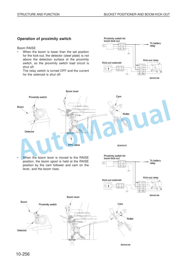
- 4.68. Bucket positioner and boom kickout
- 4.69. Machine monitor system
- 4.70. Main monitor
- 4.71. Maintenance monitor
- 4.72. Transmission autoshift control system
- 4.73. Transmission controller
- 4.75. Sensors
- 4.76. Engine start circuit
- 4.77. Ether start
- 4.78. Electric transmission control
- 4.79. Combination switch
- 4.80. Kickdown, hold switch
- 4.81. Transmission electric circuit diagram
- 4.82. Transmission cutoff switch
- 4.83. Transmission cutoff function
- 4.84. Electric parking brake control
- 4.85. Airconditioner
- 4.86. Wiring diagrams
- 5. Testing and adjusting
- 5.1. Standard value table for engine
- 5.2. Standard value table for chassis
- 5.3. Test certificate
- 5.4. Standard value table for electrical parts
- 5.5. Tools for testing, adjusting and troubleshooting
- 5.6. Adjusting valve clearance
- 5.7. Measuring compression pressure
- 5.8. Measuring blowby pressure
- 5.9. Testing and adjusting fuel injection timing
- 5.10. Mesuring exhaust color
- 5.11. Measuring intake air pressure (boost pressure)
- 5.12. Measuring engine oil pressure
- 5.13. Testing the fan belt tension
- 5.14. Measuring accelerator pedal
- 5.15. Basic adjustment of accelerator pedal
- 5.16. Measuring operating force, travel of speed lever
- 5.17. Measuring stall speed
- 5.18. Measuring torque converter, transmission, parking brake oil pressure
- 5.19. Method of operating emergency manual spool
- 5.20. Measuring clearance between tyre and wheel
- 5.21. Measuring operating force of steering wheel
- 5.22. Measuring steering oil pressure
- 5.23. Measuring operating force, travel of brake pedal
- 5.24. Measuring brake performance
- 5.25. Testing brake oil pressure
- 5.26. Measuring brake disc wear
- 5.27. Bleeding air from brake system
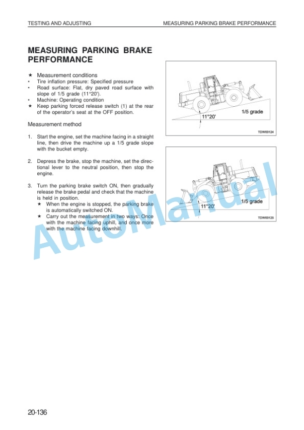
- 5.28. Measuring parking brake performance
- 5.29. Method of manual release of parking brake
- 5.30. Testing wear of parking brake disc
- 5.31. Measuring work equipment control lever
- 5.32. Measuring PPC valve pressure
- 5.33. Measuring work equipment
- 5.34. Testing and adjusting bucket positioner
- 5.35. Testing and adjusting boom kickout
- 5.36. Adjusting main monitor (speedometer modul)
- 5.37. Checking for abnormality in fuel level sensor
- 5.38. Troubleshooting
- 5.39. Points to remember when troubleshooting
- 5.40. Sequence of events in troubleshooting
- 5.41. Precautions when carrying out maintenance
- 5.42. Handling connectors
- 5.43. Checks before troubleshooting
- 5.44. Method of using troubleshooting charts
- 5.45. Connector types and mounting locations, connector pin arrangement diagram
- 5.46. Connection table for connector pin numbers
- 5.47. Troubleshooting of engine system (S mode)
- 5.48. Troubleshooting of main monitor system (M mode)
- 5.49. Troubleshooting of maintenance monitor system (K mode)
- 5.50. Troubleshooting of electrical system (E mode)
- 5.51. Troubleshooting of transmission controller system (A mode)
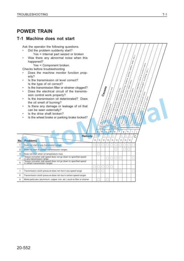
- 5.52. Troubleshooting of hydraulic and mechanical system (Chassis related) (T mode)
- 5.53. Troubleshooting of ECSS (Electronically Controlled Suspension System) (D mode)
- 6. Disassembly and assembly
- 6.1. Method of using manual
- 6.2. Precautions when carrying out operation
- 6.3. Special tool list
- 6.4. Starting motor
- 6.5. Alternator
- 6.6. Engine oil cooler
- 6.7. Fuel injection pump
- 6.8. Water pump
- 6.9. Turbocharger
- 6.10. Thermostat
- 6.11. Cylinder head
- 6.12. Torque converter charging pump
- 6.13. Torque converter, transmission
- 6.14. Torque converter
- 6.15. Tranmission
- 6.16. Transmission clutch pack
- 6.17. Parking brake
- 6.18. Transmission control valve
- 6.19. Transmission accumulator valve
- 6.20. Drive shaft
- 6.21. Front axle
- 6.22. Rear axle
- 6.23. Front differential
- 6.24. Rear differential
- 6.25. Differential
- 6.26. Final drive
- 6.27. Center hinge pin
- 6.28. Steering, orbit roll
- 6.29. Steering valve
- 6.30. Steering, switch pump
- 6.31. Steering cylinder
- 6.32. Brake valve
- 6.33. Right brake valve (tandem)
- 6.34. Left brake valve (single)
- 6.35. Slack adjuster
- 6.36. Brake
- 6.37. Parking brake disc
- 6.38. Hydraulic tank
- 6.39. Work equipment, PPC pump
- 6.40. PPC valve
- 6.41. Main control valve
- 6.42. Bucket cylinder
- 6.43. Boom cylinder
- 6.44. Hydraulic cylinder
- 6.45. Maintenance monitor
- 6.46. Air conditioner unit
- 6.47. Air conditioner condenser
- 6.48. Dry receiver
- 6.49. Air conditioner compressor
- 7. Maintenance standard
- 7.1. Engine mount, transmission mount
- 7.2. Torque converter
- 7.3. Transmission
- 7.4. Transmission control valve
- 7.5. Drive shaft
- 7.6. Diffential
- 7.7. Final drive
- 7.8. Axle mount
- 7.9. Steerig column, orbit roll
- 7.10. Steering valve
- 7.11. Steering cylinder mount
- 7.12. Slack adjuster
- 7.13. Brake valve
- 7.14. Brake
- 7.15. Parking brake
- 7.16. Torque converter, transmission pump
- 7.17. Steering, switch pump
- 7.18. Hydraulic, PPC pump
- 7.19. PPC valve
- 7.20. Cutoff valve
- 7.21. Main control valve
- 7.22. Boom cylinder
- 7.23. Bucket cylinder
- 7.24. Center hinge pin
- 7.25. Work equipment linkage
- 7.26. Bucket
- 7.27. Bucket positioner and boom kickout


There are no reviews yet.