
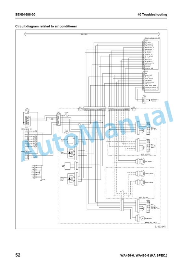
Description
-
Model List:
- WA450-6 Galeo Wheel Loader
- WA480-6 Galeo Wheel Loader
- 1. MAIN MENU
- 2. COVER PAGE
- 3. Index and foreword
- 3.1. Index
- 3.1.1. Composition of shop manual
- 3.1.2. Table of contents
- 3.2. Foreword and general information
- 3.2.1. Safety notice
- 3.2.2. How to read the shop manual
- 3.2.3. Explanation of terms for maintenance standard
- 3.2.4. Handling electric equipment and hydraulic component
- 3.2.5. Precautions when carrying out operation
- 3.2.6. Method of disassembling and connecting pushpull type coupler
- 3.2.7. Standard tightening torque table
- 3.2.8. Conversion table
- 4. Specification
- 4.1. Specification and technical data
- 4.1.1. Specification and technical data
- 5. Structure, function and maintenance standard
- 5.1. Engine and cooling system
- 5.1.1. Engine and cooling system
- 5.1.2. Engine mount and transmission mount
- 5.1.3. Cooling system
- 5.1.4. Cooling fan pump
- 5.1.5. Cooling fan motor
- 5.2. Power train
- 5.2.1. Power train
- 5.3. Steering system
- 5.3.1. Steering system
- 5.4. Brake system
- 5.4.1. Brake system
- 5.5. Undercarriage and frame
- 5.5.1. Undercarriage and frame
- 5.5.2. Tires
- 5.6. Hydraulic system, Part 1
- 5.6.1. Hydraulic system, Part 1
- 5.6.2. Hydraulic piping diagram
- 5.6.3. Work equipment control lever linkage
- 5.6.4. Hydraulic tank
- 5.6.5. Power train pump
- 5.6.6. Work equipment pump
- 5.6.7. Work equipment control valve
- 5.6.8. CLSS
- 5.6.9. Each function and operation of each valve
- 5.7. Hydraulic system, Part 2
- 5.7.1. Hydraulic system, Part 2
- 5.8. Work equipment
- 5.8.1. Work equipment
- 5.9. Cab and its attachments
- 5.9.1. Cab and its attachments
- 5.10. Electrical system, Part 1
- 5.10.1. Electrical system, Part 1
- 5.11. Electrical system, Part 2
- 5.11.1. Electrical system, Part 2
- 5.12. Electrical system, Part 3
- 5.12.1. Electrical system, Part 3
- 6. Standard value table
- 6.1. Standard service value table
- 6.1.1. Standard value table for engine
- 6.1.2. Standard value table for chassis
- 7. Testing and adjusting
- 7.1. Testing and adjusting, Part 1
- 7.1.1. Testing and adjusting, Part 1
- 7.2. Testing and adjusting, Part 2
- 7.2.1. Testing and adjusting, Part 2
- 7.3. Testing and adjusting, Part 3
- 7.3.1. Testing and adjusting, Part 3
- 8. Troubleshooting
- 8.1. Failure code table and fuse locations
- 8.1.1. Failure code table and fuse locations
- 8.2. General information on troubleshooting
- 8.2.1. General information on troubleshooting
- 8.3. Troubleshooting by failure code (Display of code), Part 1
- 8.3.1. Troubleshooting by failure code (Display of code), Part 1
- 8.4. Troubleshooting by failure code (Display of code), Part 2
- 8.4.1. Troubleshooting by failure code (Display of code), Part 2
- 8.5. Troubleshooting by failure code (Display of code), Part 3
- 8.5.1. Troubleshooting by failure code (Display of code), Part 3
- 8.6. Troubleshooting by failure code (Display of code), Part 4
- 8.6.1. Troubleshooting by failure code (Display of code), Part 4
- 8.7. Troubleshooting by failure code (Display of code), Part 5
- 8.7.1. Troubleshooting by failure code (Display of code), Part 5
- 8.8. Troubleshooting by failure code (Display of code), Part 6
- 8.8.1. Troubleshooting by failure code (Display of code), Part 6
- 8.9. Troubleshooting by failure code (Display of code), Part 7
- 8.9.1. Troubleshooting by failure code (Display of code), Part 7
- 8.9.2. Failure code DHPCKX (Lift arm cylinder bottom pressure sensor Out of input signal range)
- 8.9.3. Failure code DHPDKX (Lift arm cylinder head pressure sensor Out ofinput signal range)
- 8.9.4. Failure code DHT1KX (Transmission cutoff pressure sensor Out of input signal range)
- 8.9.5. Failure code DHT8KA (Steering pump pressure sensor Disconnection)
- 8.9.6. Failure code DHT8KB (Steering pump pressure sensor Short circuit)
- 8.9.7. Failure code DK59KA (Lift arm EPC lever potentiometer (Main) Disconnection)
- 8.9.8. Failure code DK59KY (Lift arm EPC lever potentiometer (Main) Short circuit with power supply line)
- 8.9.9. Failure code DK59L8 (Lift arm EPC lever potentiometer (Main) Analog signals disagree)
- 8.9.10. Failure code DK5AKA (Lift arm EPC lever potentiometer (Sub) Disconnection)
- 8.9.11. Failure code DK5AKY (Lift arm EPC lever potentiometer (Sub) Short circuit with power supply line)
- 8.9.12. Failure code DK5BKA (Bucket EPC lever potentiometer (Main) Disconnection)
- 8.9.13. Failure code DK5BKY (Bucket EPC lever potentiometer (Main) Short circuit with power supply line)
- 8.9.14. Failure code DK5BL8 (Bucket EPC lever potentiometer (Main) Analog signals disagree)
- 8.9.15. Failure code DK5CKA (Bucket EPC lever potentiometer (Sub) Disconnection)
- 8.9.16. Failure code DK5CKY (Bucket EPC lever potentiometer (Sub) Short circuit with power supply line)
- 8.9.17. Failure code DK5DKA (3spool valve (attachment) EPC lever potentiometer (Main) Disconnection)
- 8.9.18. Failure code DK5DKY (3spool valve (attachment) EPC lever potentiometer (Main) Short circuit with power supply line)
- 8.9.19. Failure code DK5DL8 (3spool valve (attachment) EPC lever potentiometer (Main) Analog signals disagree)
- 8.9.20. Failure code DK5EKA (3spool valve (attachment) EPC lever potentiometer (Sub) Disconnection)
- 8.9.21. Failure code DK5EKY (3spool valve EPC lever potentiometer (Sub) Short circuit with power supply line)
- 8.10. Troubleshooting by failure code (Display of code), Part 8
- 8.10.1. Troubleshooting by failure code (Display of code), Part 8
- 8.11. Troubleshooting by failure code (Display of code), Part 9
- 8.11.1. Troubleshooting by failure code (Display of code), Part 9
- 8.12. Troubleshooting by failure code (Display of code), Part 10
- 8.12.1. Troubleshooting by failure code (Display of code), Part 10
- 8.13. Troubleshooting of electrical system (Emode)
- 8.13.1. Troubleshooting of electrical system (Emode)
- 8.14. Troubleshooting of hydraulic and mechanical system (Hmode)
- 8.14.1. Troubleshooting of hydraulic and mechanical system (Hmode)
- 8.15. Troubleshooting of engine (Smode)
- 8.15.1. Troubleshooting of engine (Smode)
- 8.15.2. Method of using troubleshooting chart
- 9. Disassembly and assembly
- 9.1. General information on disassembly andassembly
- 9.1.1. General information on disassembly and assembly
- 9.1.2. How to read this manual
- 9.1.3. Coating materials list
- 9.1.4. Special tools list
- 9.1.5. Sketches of special tools
- 9.2. Engine and cooling system
- 9.2.1. Engine and cooling system
- 9.3. Power train, Part 1
- 9.3.1. Power train, Part 1
- 9.4. Power train, Part 2
- 9.4.1. Power train, Part 2
- 9.5. Undercarriage and frame
- 9.5.1. Undercarriage and frame
- 9.6. Hydraulic system
- 9.6.1. Hydraulic system
- 9.6.2. Removal and installation of steering demand valve assembly
- 9.6.3. Removal and installation of work equipment valve assembly
- 9.6.4. Removal and installation of brake charge valve assembly
- 9.6.5. Removal and installation of hydraulic tank assembly
- 9.6.6. Removal and installation ofsteering and power train pump assembly
- 9.6.7. Removal and installation of workequipment and cooling fan pump assembly
- 9.7. Work equipment
- 9.7.1. Work equipment
- 9.8. Cab and its attachments
- 9.8.1. Cab and its attachments
- 9.9. Electrical system
- 9.9.1. Electrical system
- 10. Diagrams and drawings
- 10.1. Hydraulic diagrams and drawings
- 10.1.1. Hydraulic diagrams and drawings
- 10.1.2. Power train hydraulic circuit diagram
- 10.1.3. Hydraulic circuit diagram
- 10.2. Electrical diagrams and drawings
- 10.2.1. Electrical diagrams and drawings



There are no reviews yet.