

Description
-
Model List:
- WF550-3 Trash Compactor
- WF550T-3 Trash Compactor
- 1. WF5503 / WF550T3
- 2. CONTENTS
- 3. SAFETY
- 3.1. Safety notice
- 3.2. Foreword
- 3.3. How to read the shop manual
- 3.4. Hoisting instructions
- 4. STRUCTURE AND FUNCTION
- 4.1. General
- 4.2. Drive unit cooling fan
- 4.3. Transmission
- 4.4. Main relief, torque converter relief valve
- 4.5. Axle
- 4.6. Differential
- 4.7. Limited slip differential
- 4.8. Final drive
- 4.9. Axle mount, center hinge pin
- 4.10. Steering piping
- 4.11. Brake piping
- 4.12. Brake
- 4.13. Parking brake emergency release solenoid valve
- 4.14. Hydraulic piping
- 4.15. Work equipment lever linkage
- 4.16. Hydraulic tank
- 4.17. PPC valve
- 4.18. Cutoff valve
- 4.19. Main control valve
- 4.20. Main relief valve
- 4.21. Suction valve
- 4.22. Float selector valve and unload valve
- 4.23. Operation (WF550T3)
- 4.24. Operation (WF5503)
- 4.25. Bucket positioner and boom kickout (WF5503)
- 4.26. Air conditioner
- 4.27. Machine monitor system
- 4.28. Main monitor
- 4.29. Maintenance monitor
- 4.30. Transmission controller
- 4.31. Electric transmission control
- 5. TESTING AND ADJUSTING
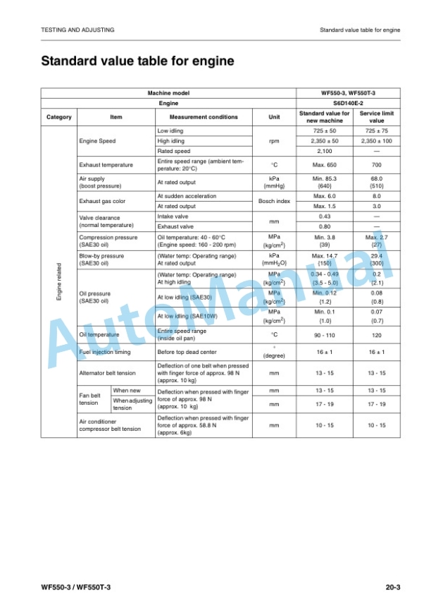
- 5.1. Standard value table for engine
- 5.2. Standard value table for chassis
- 5.3. Standard value table for electrical parts
- 5.4. Table of required tools
- 5.5. Sketch of special tools
- 5.6. Measuring blowby pressure
- 5.7. Measuring engine oil pressure
- 5.8. Adjusting speed sensor
- 5.9. Adjusting of engine stop motor cable
- 5.10. Torque converter and transmission oil pressure
- 5.11. Steering oil pressure
- 5.12. Measuring parking brake oil pressure
- 5.13. Testing and adjusting PPC oil pressure
- 5.14. Adjusting PPC valve linkage
- 5.15. Work equipment hydraulic pressure
- 5.16. Adjusting work equipment lever linkage
- 5.17. Adjusting main monitor (speedometer module)
- 6. TROUBLESHOOTING
- 6.1. Outline
- 6.2. Connector types and mounting locations
- 6.3. Connector arrangement diagram
- 7. TROUBLESHOOTING FOR RADIATOR COOLING FAN SYSTEM (EC MODE)
- 7.1. Electric circuit diagram of cooling fan system
- 7.2. EC1 Fan does not rotate (selector switch position AUTO)
- 8. TROUBLESHOOTING OF HYDRAULIC AND MECHANICAL SYSTEM (H MODE)
- 8.1. H1 Blade does not move
- 8.2. H2 Blade is slow or blade lacks power
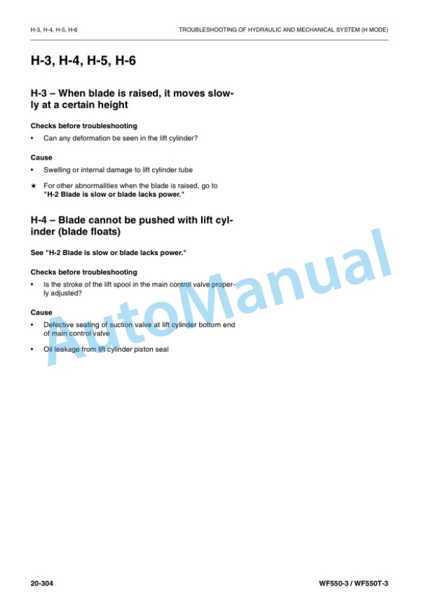
- 8.3. H3, H4, H5, H6
- 9. DISASSEMBLY AND ASSEMBLY
- 9.1. Special tool list
- 9.2. Sketches of special tools
- 9.3. Starting motor assembly
- 9.4. Engine front seal
- 9.5. Radiator assembly
- 9.6. Engine assembly
- 9.7. Front axle assembly
- 9.8. Front differential assembly
- 9.9. Rear axle assembly
- 9.10. Rear differential assembly
- 9.11. Differential gear assembly
- 9.12. Final drive assembly
- 9.13. Steering cylinder assembly
- 9.14. Steering valve assembly
- 9.15. Slack adjuster assembly
- 9.16. Hydraulic tank assembly
- 9.17. PPC valve assembly
- 9.18. Main control valve assembly
- 9.19. Lift cylinder assembly
- 9.20. Boom, bucket and lift cylinders assembly
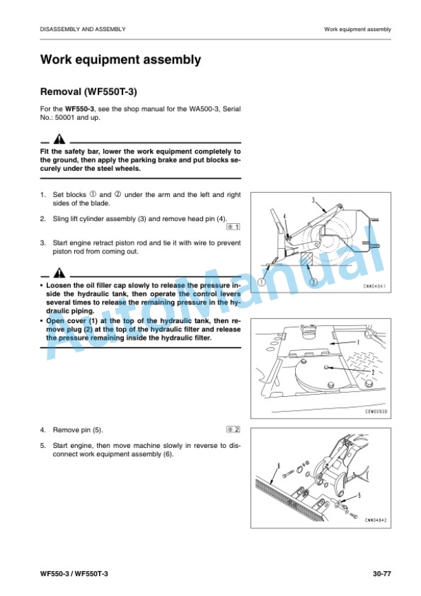
- 9.21. Work equipment assembly
- 9.22. Engine hood assembly
- 9.23. Floor frame assembly
- 9.24. Fuel tank assembly
- 9.25. Air conditioner condenser assembly
- 9.26. Reciver tank
- 10. MAINTENANCE STANDARD
- 10.1. Engine mount
- 10.2. Transmission mount
- 10.3. Damper
- 10.4. Torque converter charging pump
- 10.5. Torque converter, PTO
- 10.6. Transmission
- 10.7. Transfer
- 10.8. Main relief, torque converter relief valve
- 10.9. Lubrication relief valve
- 10.10. Center hinge pin
- 10.11. Steering column
- 10.12. Steering pump
- 10.13. Steering valve
- 10.14. Steering cylinder mount
- 10.15. Switch, PPC pump
- 10.16. PPC valve
- 10.17. Main control valve
- 10.18. Cutoff valve
- 10.19. Hydraulic cylinders
- 10.20. Work equipment linkage
- 10.21. Bucket positioner and boom kickout
- 10.22. ROPS cab
- 11. OTHERS
- 11.1. Hydraulic circuit diagram for power train
- 11.2. Brake circuit diagram
- 11.3. Electric circuit for cooling fan
- 11.4. Work equipment hydraulic circuit diagram (WF550T3)
- 11.5. Work equipment hydraulic circuit diagram (WF5503)
- 11.6. Electric circuit diagram (1/4)
- 11.7. Electric circuit diagram (2/4)
- 11.8. Electric circuit diagram (3/4)
- 11.9. Electric circuit diagram (4/4)



There are no reviews yet.