
Description
-
Model List:
- 5400 Series Tractors
- 1. Introduction
- 2. A . Using the manual
- 3. B . Specifications
- 4. C . Ground speed
- 5. D . General dimensions
- 6. E . Capacities
- 7. F . Conversion tables
- 8. G . Locking compounds and seal-ants
- 9. Engine
- 10. Perkins engine – General
- 11. A . Introduction
- 12. B . Specifications and standards
- 13. C . Main characteristics
- 14. Gearbox
- 15. General – GBA20 with Power Shuttle
- 16. A . General
- 17. B . Construction and description
- 18. C . Operation
- 19. D . Specifications of the GBA20 transmission assembly with Power Shuttle
- 20. GBA20 input unit with mechanical reverse shuttle
- 21. A . General
- 22. B . Removing and refitting the input unit
- 23. C . Service tools
- 24. Input unit – GBA20 with Power Shuttle
- 25. A . General
- 26. B . Preliminary operations
- 27. C . Removal
- 28. D . Refitting
- 29. E . Adjusting the progressivity sensor
- 30. F . Final operations
- 31. G . Service tools
- 32. GBA20 mechanical reverse shuttle
- 33. A . General
- 34. B . Operation
- 35. C . Preliminary operations
- 36. D . Disassembling and reassembling the reverse shuttle
- 37. E . Shimming the secondary shaft
- 38. F . Final operations
- 39. GBA20 Power Shuttle
- 40. A . General
- 41. B . Removing and refitting the forward clutch
- 42. C . Disassembling and reassembling the forward clutch
- 43. D . Shimming the forward clutch
- 44. E . Disassembling and reassembling the reverse clutch
- 45. F . Disassembling and reassembling the driving pinion
- 46. G . Service tools
- 47. GBA20 Speedshift with Power Shuttle
- 48. A . General
- 49. B . Operation
- 50. C . Preliminary operations
- 51. D . Removing and disassembling the front cover
- 52. E . Removing, splitting and disas-sembling the planet carrier assembly
- 53. F . Disassembling the hydraulic cover
- 54. G . Assembling the planet carrier
- 55. H . Refitting the hydraulic cover
- 56. I . Assembling the planet carrier
- 57. J . Assembling and refitting the front cover
- 58. K . Final operations
- 59. Selector cover – GBA20 with Power Shuttle
- 60. A . General
- 61. B . Operation
- 62. C . Removing and refitting the cover
- 63. D . Disassembling and reassembling the selector mechanisms
- 64. E . Fitting and adjusting the gear linkage
- 65. GBA20 selector rails with mechanical reverse shuttle
- 66. A . General
- 67. B . Servicing guide
- 68. C . Creeper fork
- 69. D . Hare / Tortoise fork and lock- 1st /2nd – 3rd / 4th fork assembly and selector rail
- 70. E . Mechanical reverse shuttle selector
- 71. F . Service tools
- 72. GBA20 selector rail with Power Shuttle
- 73. A . General
- 74. B . Servicing guide
- 75. C . Creeper fork
- 76. D . Hare / Tortoise fork and lock- 1st /2nd – 3rd / 4th fork assembly and selector rail
- 77. E . Service tools
- 78. GBA20 output shaft with Power Shuttle
- 79. A . General
- 80. B . Preliminary operations
- 81. C . Removing and refitting the selector rail and the forks
- 82. D . Removing, refitting and shim-ming the shaft
- 83. E . Final operations
- 84. GBA20 mainshaft with Power Shuttle
- 85. A . General
- 86. B . Preliminary operations
- 87. C . Disassembling and reassembling the shaft
- 88. D . Final operations
- 89. E . Service tools
- 90. GBA20 layshaft with Power Shuttle
- 91. A . General
- 92. B . Preliminary operations
- 93. C . Removing and refitting the shaft and pinion assembly
- 94. D . Removing and refitting pinions
- 95. E . Replacing the taper roller bear-ings and the layshaft
- 96. F . Shimming the pinions
- 97. G . Shimming the shaft
- 98. H . Final operations
- 99. I . Service tool
- 100. GBA20 Creeper unit
- 101. A . General
- 102. C . Removing the creeper unit and the ring gear
- 103. E . Reassembling the planet carrier, refitting the ring gear and the unit
- 104. F . Final operations
- 105. G . Adjusting the control
- 106. Rear axle
- 107. General – GPA20 operation
- 108. A . General
- 109. B . Centre housing assembly
- 110. GPA20 Normal Duty Trumpet housings
- 111. A . General
- 112. B . Trumpet assembly
- 113. C . Planet carrier
- 114. D . Bearings and seals
- 115. E . Preloading the axle shaft bear-ings
- 116. F . Replacing a lug stud
- 117. GPA20 Heavy Duty Trumpet housings
- 118. A . General
- 119. B . Trumpet assembly
- 120. C . Planet carrier
- 121. D . Bearings and seals
- 122. E . Preloading the axle shaft bear-ings
- 123. F . Replacing a wheel stud
- 124. GPA20 brake piston
- 125. A . General
- 126. B . Disassembly
- 127. C . Reassembly
- 128. GPA20 handbrake unit and control
- 129. A . General
- 130. B . Operation
- 131. C . Disassembly
- 132. D . Reassembly
- 133. E . Assembling and adjusting the control
- 134. GPA20 differential
- 135. A . General
- 136. B . Removing the left-hand flange and differential lock assembly
- 137. C . Disassembling and reassembling the differential lock assembly
- 138. D . Refitting the left-hand flange and the differential lock assembly
- 139. E . Removing the differential assembly
- 140. F . Disassembling the differential assembly and the ring gear
- 141. G . Removing and disassembling the drive pinion
- 142. H . Reassembling the ring gear and differential assembly
- 143. I . Adjusting the bevel gear distance, refitting and shimming of the drive pinion
- 144. J . Refitting and shimming of the differential assembly
- 145. K . Adjusting and checking the back-lash
- 146. L . Service tools
- 147. GPA20 hitch / Linkage
- 148. A . General
- 149. B . Removal
- 150. C . Disassembly
- 151. D . Reassembly
- 152. E . Refitting
- 153. F . Rear Hitch
- 154. G . Presentation of the hitch
- 155. H . Disassembling and reassembling a lift ram
- 156. GPA20 hitch hooks
- 157. A . General
- 158. B . Presentation of the different hitch hooks
- 159. C . Adjusting automatic hook tie-rods and controls
- 160. D . Operating principle of the Dromone retractable hook
- 161. GPA20 rear wheels / hubs
- 162. A . General
- 163. B . Description of rear axle wheel assembly
- 164. C . Changing wheel track spacing
- 165. D . Replacing a wheel stud
- 166. Power take off
- 167. General – GPA20 operation
- 168. A . General
- 169. B . Existing power take-off types
- 170. Intermediate shaft – Driving pinions – GPA20 brake
- 171. A . General
- 172. B . Operation
- 173. C . 2-speed PTO (without shimming)
- 174. D . 2-speed PTO (with shimming)
- 175. E . 4-speed economy PTO (without shimming)
- 176. F . 4-speed LSPTO (with shimming)
- 177. G . Assembling and adjusting the 4-speed LSPTO control
- 178. GPA20 removable shaft
- 179. A . General
- 180. B . Replacing the 540 or 1000 rpm shaft
- 181. C . Removing and refitting the rear bearing
- 182. D . Disassembling and reassembling the rear bearing
- 183. E . Disassembling and assembling the 540 and 1000 rpm pinions and the front bearing
- 184. GPA20 shiftable shaft
- 185. A . General
- 186. C . Removing and refitting the rear bearing
- 187. D . Disassembling and reassembling the rear bearing
- 188. E . Disassembling and reassembling the pinions (540 and 1000 rpm) and the front shaft bearing
- 189. F . Controls
- 190. G . Flange shaft
- 191. H . Shaft with reinforced sealing
- 192. GPA20 – GSPTO
- 193. A . General
- 194. B . Operation
- 195. C . Disassembling the power take off (2WD version)
- 196. D . Reassembling the power take off (2WD version)
- 197. E . Disassembling the power take off (4WD version)
- 198. F . Reassembling the power take off (4WD version)
- 199. G . Assembling and adjusting the control
- 200. Front axle
- 201. A . General description
- 202. B . Characteristics and dimensions
- 203. C . Product identification
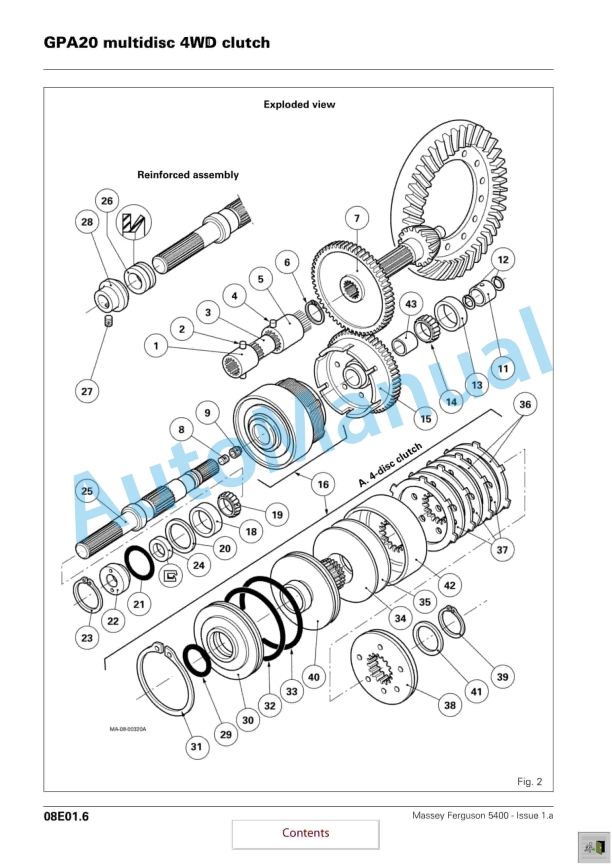
- 204. GPA20 multidisc 4WD clutch
- 205. A . General
- 206. B . Operation
- 207. C . Removing the clutch assembly
- 208. D . Disassembling the clutch
- 209. E . Reassembling the clutch
- 210. F . Refitting the clutch assembly
- 211. G . Locally made tools
- 212. Hydraulics
- 213. Description of circuit open centre 57 l/mn
- 214. A . General
- 215. B . Low flow rate, low pressure circuit
- 216. C . Layout of main components of Power shuttle and Speedshift circuit
- 217. D . Layout of main components of Mechanical reverse shuttle Speedshift circuit
- 218. E . High flow rate, high pressure circuit
- 219. F . Diagram of mechanical reverse shuttle Speedshift
- 220. G . Diagram of Power shuttle Speedshift
- 221. Right-hand cover 57l/min Open Centre
- 222. A . General
- 223. B . Identification of channels and ports
- 224. C . Removing and refitting the cover
- 225. D . Disassembling and reassembling the high pressure valve



There are no reviews yet.